Practical millimeter-wave holographic imaging system with good robustness  Download: 993次
With the growing threat of terrorism around the world nowadays, security detection of airplane passengers is becoming more and more important[1]. Conventional systems for security detection include metal detectors for personnel and x ray scanners for luggage. Compared with these methods, millimeter-wave (MMW) imaging is more effective and safe. MMW imaging combines the advantages of both optical and microwave imaging systems, particularly the high resolution of optical imaging due to the short wavelength and penetration through most clothing of microwave imaging. Moreover, holographic techniques can be easier to achieve in the MMW band than optic waves, as we can get the amplitude and phase of the MMW signal easily. Additionally, the extreme development of MMW chips, modules and communication and system techniques make MMW security detection possible[2
MMW imaging can be classified as a passive imaging system and an active imaging system. There is no illuminating source in a passive system[10
Because of the advantages of MMW imaging systems, we present an active MMW holographic imaging system. A practical system has been realized in our lab, and good robustness of the system is achieved. When it comes to the word “practical,” we mean the system can work even if some useful electromagnetic information is missing, which could happen in practical, complicated circumstances. In other words, the system does not just work in a perfect lab environment. The less electromagnetic data is necessary when reconstructing the image, the more practical the system is. First, the imaging system is described in detail, and then the imaging algorithm is presented. Next, an analysis of the robustness of the imaging system through the peak signal-to-noise ratio (PSNR) is demonstrated. Finally, conclusions are drawn at the end of the Letter.
A practical implementation of an MMW holographic imaging system is performed. It takes quite a long time to scan a single transceiver over the whole aperture, and it is costly and complex to make two-dimensional arrays without mechanical scanning. Taking the working time and the cost of the system into account, we choose to scan a line of transmitting and receiving antennas array row by row. A line of transceivers is scanned over the aperture that has the target to collect the data. Although the transmitting and receiving antennas are separate, they are at approximately the same location, and may be assumed to be at the middle point. The diagram of our MMW holographic imaging system is shown in Fig.
This system can reconstruct a three-dimensional (3D) image of the target as wideband frequency (28–33 GHz) signals are recorded. A high-stability MMW frequency source is applied here to achieve the transmitting signal. We choose 64 frequencies at an interval of 80 MHz. Two levels of SP8T switches are adopted to achieve a row of 64 T/R units. The switching and moving of the antenna array is controlled by a logic circuit. We record both the in-phase and quadrature signals (called I and Q, respectively) after mixing the receiving signals reflected by the target with the transmitting ones from MMW oscillators, that is to say, both the amplitude and phase can be obtained. Then, the intermediate frequency (IF) signals are digitized by an eight-unit analog to digital (AD) converter and stored in the computer. Finally, the imaging algorithm discussed in the next is applied here to reconstruct the image.
The distance between the antenna element is chosen to be 6 mm, which is a little larger than half the wavelength of 5 mm, since the real beam of the antenna is not infinity. The size of the scanning aperture is
The measurement configuration is shown in Fig.
Assuming the reflection coefficient of the target at point
According to optical knowledge, a sphere wave from one point can be decomposed into infinite plane waves from the same point, which is shown in
In other words, the image of the target
FT and FT-1 here mean the Fourier transform and inverse Fourier transform, respectively.
According to the MMW holographic imaging system and imaging algorithm presented before, the point-spread function of the system is shown in Fig.
As a multi-channel system, the differences between different channels must be carefully dealt with, so we will implement system calibration first. To describe the signal in each channel, two measurements are collected.
Then, we take
The PSNR is most often used to measure the reconstruction image quality compared with the original one. Because the factor PSNR has a wide dynamic range, it is usually expressed in terms of a logarithmic decibel scale. The PSNR is defined via the mean squared error (MSE). Given two images (
The image is presented in
Obviously, the higher the PSNR is, the better the quality of the reconstructed image is.
As a multi-channel and multi-frequency system, technique fault could happen to any channel and frequency, so the robustness of the practical MMW holographic imaging system is very important. What follows is how the factor PSNR is used to analyze the robustness of our imaging system. First, we assume the data recorded from some channels at some specified frequencies are abnormal and set to zero; second, the PSNRs of the reconstructed image now and the original are calculated; and finally, the numerical value of the PSNR is used to demonstrate the degree of deterioration of the systems.
If the PSNR remains high when lots of the original electromagnetic information is missing, which could happen in a practical circumstance, we can say the robustness of the system is pretty good. In another word, the MMW holographic imaging system could still work well even if the data collected in some channels and frequencies are incorrect. To drop the influence of the image process operation, the original reconstructed image without further manipulation is utilized directly. Figure

Fig. 5. Original reconstructed image of a person with hands raised (front, side, and top views of the picture).
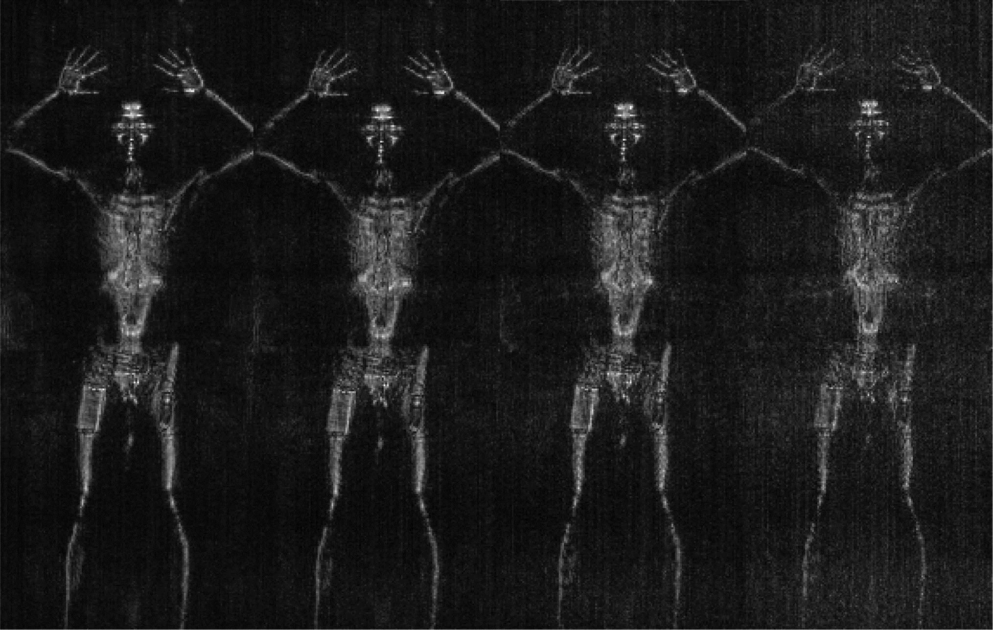
If we set 20%, 40%, 60%, 80% of the electromagnetic data to zero randomly, the reconstructed images are shown in Fig.

Fig. 6. Reconstructed images with different percentages of electromagnetic data missing.
Comparisons of the different results in Fig.
In conclusion, a holographic MMW active imaging system with good robustness is investigated. The working frequency band of this system is from 28 to 33 GHz. The imaging results of different circumstances are presented. The PSNR remains high when 40% of the original electromagnetic information is missing, which indicates that the robustness of our system is high. However, there are still some drawbacks in the imaging system. For instance, after the proper image processing operation, the system only gives the outline of the target without the material chemical properties, so the indicator can only rely on the imaging clues to distinguish if the object is safe or dangerous and needs to be removed to be further tested.
[2]
[3]
[4]
[5]
[6]
[7]
[8]
[9]
[10]
[11]
[12]
[13]
[14]
[15]
[16]
[17]
[18]
[19]
[20]
[21]
[22]
[23]
[24]
Yukun Zhu, Minghui Yang, Liang Wu, Yun Sun, Xiaowei Sun. Practical millimeter-wave holographic imaging system with good robustness[J]. Chinese Optics Letters, 2016, 14(10): 101101.


