Chinese Optics Letters, 2019, 17 (7): 070602, Published Online: Jul. 12, 2019   

Performance improvement in double-ended RDTS by suppressing the local external physics perturbation and intermodal dispersion Download: 863次

Author Affiliations
1 Key Laboratory of Advanced Transducers and Intelligent Control System, Ministry of Education and Shanxi Province, Taiyuan 030024, China
2 College of Physics & Optoelectronics, Taiyuan University of Technology, Taiyuan 030024, China
Abstract
We propose and experimentally demonstrate a novel Raman-based distributed fiber-optics temperature sensor (RDTS) for improving the temperature measurement accuracy and engineering applicability. The proposed method is based on double-ended demodulation with a reference temperature and dynamic dispersion difference compensation method, which can suppress the effect of local external physics perturbation and intermodal dispersion on temperature demodulation results. Moreover, the system can omit the pre-calibration process by using the reference temperature before the temperature measurement. The experimental results of dispersion compensation indicate that the temperature accuracy optimizes from 5.6°C to 1.2°C, and the temperature uncertainty decreases from 16.8°C to 2.4°C. Moreover, the double-ended configuration can automatically compensate the local external physics perturbation of the sensing fiber, which exhibits a distinctive improvement.

Distributed fiber temperature sensors exploit specific optical effects along optical fibers to obtain a spatially distributed profile of environmental temperature[13" target="_self" style="display: inline;">–3]. The Raman distributed temperature sensor (RDTS), based on spontaneous Raman backscattering and optical domain reflectometry[4], has been studied for many years. Recently, the RDTS system has been widely applied in areas such as gas pipeline, smart grids, and road tunnel for their unique sensing capabilities[57" target="_self" style="display: inline;">–7].

The temperature demodulation method is a crucial factor for improving the performance of the RDTS system. At present, there are two types of temperature demodulation methods, the self-demodulation method and dual-demodulation method. The self-demodulation method uses the Raman anti-Stokes backscattered light to determine the temperature through the sensing optical fiber[8,9]. The dual-demodulation method uses the ratio of the backscattered light of anti-Stokes over Rayleigh[10] or Stokes[1113" target="_self" style="display: inline;">–13] to demodulate the temperature. The above methods are based on the single-ended configuration for demodulating the temperature information, which means that only one end of the sensing fiber is connected to the RDTS system. However, the single-ended RDTS does not solve the problem for the temperature measurement error of RDTS being induced when local external physics perturbation is applied to the sensing fiber[14].

To decrease the measurement error due to the local external physics perturbation, the dual-ended configuration RDTS has been proposed[15], and the double-ended configuration with self-demodulation can demodulate the temperature along the sensing fiber. But, the self-demodulation method has a high demand for the stability of the system[16], which limits the temperature accuracy and engineering applicability. In addition, the temperature demodulation methods based on the single-ended and double-ended configurations must execute the pre-calibration process. It requires the entire sensing fiber to be placed in a constant temperature field[1113" target="_self" style="display: inline;">–13,15] or uses the curve fitting method[17] to compensate the different attenuation of anti-Stokes and Stokes. Once the RDTS system replaces any devices or sensing fiber, it needs to recalibrate before the temperature measurement, which greatly limits the engineering application of RDTS. Moreover, the intermodal dispersion also causes the dislocation of Stokes and anti-Stokes light at the same position of the sensing fiber, which leads to temperature measurement error in the RDTS.

In this paper, a novel double-ended RDTS system with a reference temperature and dynamic dispersion difference compensation method is proposed to improve the temperature accuracy and engineering applicability, which is available to suppress the fiber intermodal dispersion and local external physics perturbation. In addition, it can omit the pre-calibration process by using the reference temperature before the temperature measurement.

In the RDTS system, a short pulse of light is launched into the sensing fiber, generating two Raman backscattered components[18], which are measured as a function of time at the receiver side. While the intensity of the Raman down-shifted frequency component (Stokes) is only slightly temperature-dependent, the intensity of the up-shifted frequency component (anti-Stokes) strongly depends on the temperature of the sensing fiber. However, depending on the fiber attenuation and local loss, the anti-Stokes signal alone is usually not employed for absolute temperature measurements[16]. Actually, the dependence must be cancelled out by normalizing the anti-Stokes with a temperature-independent signal such as the Stokes. Thus, the ratio of anti-Stokes over Stokes intensity can be used to demodulate the temperature along the sensing fiber.

In the RDTS system, the backscattered light of Stokes and anti-Stokes is misaligned at the same position of the sensing fiber due to the fiber intermodal dispersion[13]. As shown in Fig. 1(a), the Fresnel reflection position of anti-Stokes light is in front of the Stokes light under the same sampling interval of the two channels, which is attributed to the Stokes light transferring faster than the anti-Stokes light. It inevitably induces the measurement error when the misaligned signals are used to demodulate the temperature of the sensing fiber. Therefore, the dynamic dispersion difference compensation method is proposed for correcting this measurement error. In this method, a segment of dispersion compensation fiber is placed in the RDTS system. The dispersion compensation fiber is a segment of common multimode fiber that is fused to the sensing fiber. The dynamic dispersion difference compensation method is based on the wavelength difference of Stokes light and anti-Stokes light. We establish an equation using the position of the dispersion compensation fiber and Fresnel reflection, which can be used to interpolate the position of Stokes light to match the anti-Stokes light. The steps of dynamic dispersion difference compensation method are as follows. (1) Calculating the positions of the anti-Stokes and Stokes Fresnel reflection peaks at the end of the fiber, which are expressed as L2max and L1max, respectively. (2) Locating the positions of anti-Stokes and Stokes at the dispersion calibration fiber, which can be expressed as L2 and L1, respectively. (3) The position of the Stokes light is interpolated by using Eq. (1): ϕs(L)=ϕs[(L2maxL2L1maxL1)L+L2(L2L2maxL1L1max)L1],where ϕs(L) is the intensity of the Stokes backscattered signal at the position of L. The position of the Stokes signal is consistent with the position of anti-Stokes after dispersion compensation, as shown in Fig. 1(b), and the shape of the Stokes signal is not distorted.

Fig. 1. Anti-Stokes and Stokes backscattered signal intensities (a) before the dispersion compensation and (b) after the dispersion compensation.

下载图片 查看所有图片

The dual-source calibration system[19] and the self-calibration speed algorithm[20] can also correct the effect of fiber dispersion on the RDTS. The dual-source calibration system utilizes two lasers (with a wavelength separation of 100 nm) to achieve the self-correction of the fiber dispersion. The self-calibration speed algorithm is used to calibrate the effect of fiber dispersion on the temperature demodulation of the RDTS. However, this method needs to measure the speed of Stokes and anti-Stokes before the temperature measurement. In this paper, the dynamic dispersion difference compensation method can establish an equation that uses the position of the dispersion compensation fiber and Fresnel reflection. It can calibrate the position of Stokes to match the position of anti-Stokes light. Compared with the above system, the dynamic dispersion difference compensation method does not add any devices to the RDTS, which reduces the cost of the system. In addition, this method does not require the calibration process when performing the temperature measurement.

In addition, the local fiber loss is not constant with time, since the sensing fiber may be exposed to environmental conditions that spectrally change the local fiber loss during the sensor lifetime[15]. The Raman backscattered intensity in the fiber is not only modulated by the temperature, but also related to local external physics perturbation. The traditional RDTS system based on the single-ended configuration does not consider the effect of local external physics perturbation on the temperature measurement results. Hence, significant errors can be induced when no further calibration is performed.

In order to eliminate this measurement error, the double-ended RDTS is proposed, which can obtain the forward and backward Raman backscattered signal, as shown in Fig. 2. The intensity ratio of Stokes over anti-Stokes light can be expressed as RBack(T,L)=ϕsBackϕaBack=KsKa(υsυa)4exp(hΔvkT)exp{0L[αa(L)αs(L)]dL},RFor(T,L)=ϕsForϕaFor=KsKa(υsυa)4exp(hΔvkT)exp{Ll[αa(L)αs(L)]dL}.

Fig. 2. Anti-Stokes backscattering signal intensity in both forward and backward directions.

下载图片 查看所有图片

Among them, ϕaBack and ϕsBack are the anti-Stokes and Stokes intensities of the backward direction, and ϕaFor and ϕsFor are the anti-Stokes and Stokes intensities of the forward direction. Ka and Ks are coefficients of anti-Stokes and Stokes scattering cross sections, respectively, h is the Planck’s constant, Δv is the Raman frequency shift of the fiber, k is the Boltzmann constant, T is the measurement temperature, αa and αs are the attenuation coefficients of anti-Stokes and Stokes, respectively, L is the position, and l stands for the length of the sensing fiber. The Raman intensity in the double-ended configuration RLoop(T,L) can be obtained from the geometric mean of the normalized single-ended configuration in both forward and backward directions according to RLoop(T,L)=RBack(T,L)·RFor(T,L)=KsKa(υsυa)4exp(hΔvkT)exp{0l[αa(L)αs(L)]dL}.

From Eq. (4), it can be seen that the attenuation coefficient 0l[αa(L)αs(L)]dL has no relationship with the position (L) after the forward and backward detection of the pump light. The influence of local external physics perturbation on the temperature measurement results can be eliminated. This is the key difference between the double-ended configuration RDTS and the single-ended configuration RDTS.

In order to make the Raman signal only be modulated by the temperature along the fiber, the demodulation method needs to calibrate the difference attenuation of anti-Stokes and Stokes light before the temperature measurement, which limits the engineering application of RDTS[15,17]. In the double-ended RDTS, we set up a segment of reference fiber at the front of the sensing fiber, which can generate a reference temperature. The reference signal intensity in the double-ended configuration can be obtained from the geometric mean of the normalized single-ended system in both forward and backward directions according to the following formula: RLoop(T0,L0)=RBack(T0,L0)·RFor(T0,L0)=KsKa(υsυa)4exp(hΔvkT0)exp{0l[αa(L)αs(L)]dL}.

Using Eqs. (4) and (5), we can get the temperature demodulation method from Eq. (6). The temperature along the fiber is only modulated by the Raman signal: 1T=ln[RLoop(T,L)RLoop(T0,L0)](khΔv)+1T0.

The experimental setup shown in Fig. 3 has been used to validate the proposed method for double-ended RDTS. A high-power pulsed laser operating at 1550 nm has been used with a maximum peak power of 30 W, 10 ns pulse width, and 6 kHz repetition rate. A wavelength division multiplexer (WDM) is employed to extract the backscattered anti-Stokes and Stokes Raman signal, which is then measured by the single high-sensitivity receiver consisting in a low-noise avalanche photodiode (APD), a trans-impedance amplifier (Amp), and a high-speed data acquisition card (DAC). In order to measure the temperature along the sensing fiber, the graded-index 62.5/125 multimode fiber with 13 km range has been used. The position of the reference fiber near the pulsed laser source can effectively improve the temperature measurement accuracy of the RDTS. Considering the influence of Fresnel reflection on the front end of the fiber, we place the reference fiber at the position of 80 m. The fiber under test (FUT) consists of two sections with the lengths of 15 and 16 m (FUT 1 and FUT 2). Both sensing fiber ends have been connected to the RDTS through an optical switch, which allows the pulses to be alternately sent in both forward and backward directions. In addition, FUT 1 is also used as a dispersion calibration fiber in the experiment.

Fig. 3. Experimental setup of double-ended RDTS. WDM, wavelength division multiplexer; APD, avalanche photodiode; DAC, high-speed data acquisition card; PC, personal computer.

下载图片 查看所有图片

The temperature measurement experiment based on double-ended RDTS is carried out at room temperature of 30.0°C. The sensing fiber with the length of 13.0 km is used in the experiment. The FUTs are set at a distance of 3.07 and 11.83 km, respectively. The length of each FUT is about 15 m. The temperatures of FUTs are controlled by a water bath and are set at 40°C, 45°C, 50°C, 55°C, 60°C, and 65°C. The distributed temperature results after eliminating the ground noise[13] (with 15,000 time-averaged traces) are shown in Fig. 4. The actual room temperature fluctuates by 4.2°C during the measurement time of 180 min. In addition, in the double-ended RDTS, the temperature demodulation method requires the forward and backward Raman backscattered signal to demodulate the temperature information along the sensing fiber. Since the signal-to-noise ratio of single-ended traces decreases along the sensing fiber, the measurements exhibit worse temperature resolution in the proximity of both fiber ends compared to in the middle fiber region[16]. Figure 5 stands for the temperature results of FUTs at 3.07 and 11.83 km. It can be observed that the temperature demodulation method based on double-ended RDTS can accurately detect the temperature along the 13.0 km sensing fiber. In addition, the double-ended RDTS with a reference temperature can omit the calibration process before the temperature measurement.

Fig. 4. Temperature measurement results along the sensing fiber under the temperature control of (a) 65°C, (b) 60°C, (c) 55°C, (d) 50°C, (e) 45°C, and (f) 40°C.

下载图片 查看所有图片

Fig. 5. Temperature measurement results along the FUT.

下载图片 查看所有图片

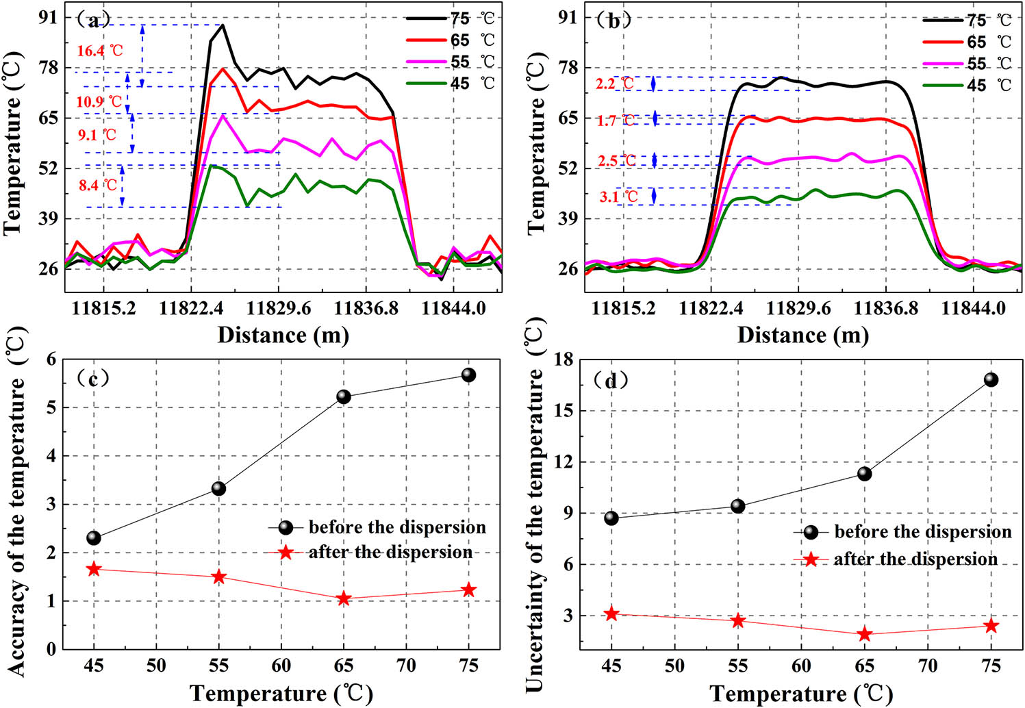
As shown in Fig. 6(a), a significant temperature rise peak appears at the beginning of FUTs due to the fiber dispersion. When the temperature of the FUTs is set at 75.0°C, the maximum measurement temperature of FUTs can reach up to 89.0°C. The experimental results show that the temperature measurement accuracy is 13.8°C, the relative error is 13.9%, and the temperature uncertainty is 16.4°C. These temperature demodulation results greatly affect the temperature measurement accuracy of RDTS, which is caused by the misalignment of Stokes and anti-Stokes signals.

Fig. 6. Temperature measurement results of FUTs. (a) Results of measured temperature before the dispersion compensation. (b) Results of measured temperature after the dispersion compensation. (c) The temperature accuracy before the dispersion compensation and after the dispersion compensation. (d) The uncertainty of temperature before and after the dispersion compensation.

下载图片 查看所有图片

In order to eliminate the misalignment information caused by fiber dispersion, the Stokes signal needs to be compensated before the temperature measurement, and Fig. 6(b) stands for the temperature demodulation results of FUTs after finishing the dispersion compensation based on Eq. (1). The experimental results show that the temperature rise peak of the FUT has disappeared, and the temperature curve has become smoother than that before dispersion compensation. Figures 6(c) and 6(d) stand for the temperature measurement accuracy and temperature uncertainty. Among them, it can be seen that the temperature accuracy optimizes from 5.6°C to 1.2°C, relative errors decrease from 7.4% to 1.6%, and the temperature uncertainty optimizes from 16.4°C to 2.4°C.

During the long-term operation of the system, the single-ended configuration RDTS cannot avoid the measurement error caused by the local external physics perturbation with the environment change. The reason for this measurement error is that the local fiber loss is inconsistent at the calibration and measurement stages. As shown in Fig. 7(a), the sensing fiber at the positions of 1.10 and 0.80 km is connected by the fiber-optic–optics connector after the sensing fiber is calibrated. In the calibration stage, the intensity ratio of Stokes over anti-Stokes light can be expressed as R(Tc,L)=ϕscBackϕacBack=KsKa(υsυa)4exp(hΔvkTc)exp{0L[αa(L)αs(L)]dL}.
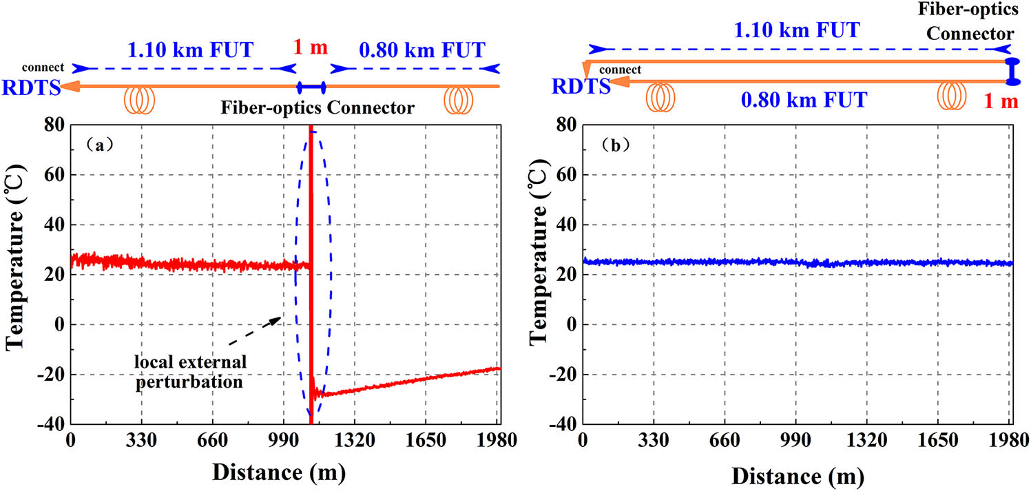
Fig. 7. Temperature demodulation results in (a) the single-ended configuration system and (b) the double-ended configuration system.

下载图片 查看所有图片

Among them, ϕacBack and ϕscBack are the anti-Stokes and Stokes intensities of the backward direction in the calibration stage. In the measurement stage, the intensity ratio of Stokes over anti-Stokes light after the fiber-optic–optics connector can be expressed as R(T,L)=ϕsBackϕaBack=KsKa(υsυa)4exp(hΔvkT)E(L)exp{0L+l[αa(L)αs(L)]dL}.

E(L) is the loss mutation coefficient of the sensing fiber, which is related to local external physics perturbation, and l is the length of the fiber-optic–optics connector. Using Eqs. (7) and (8), we can get the temperature information in 1T=ln[R(T,L)/R(Tc,L)](k/hΔv){ln[E(L)]0l[αa(L)αs(L)]dL}1+1Tc.

We can see that the Raman signal is not only modulated by the temperature, but also related to local external physics perturbation (E(L), 0l[αa(L)αs(L)]dL). As shown in Fig. 7(a), it can be observed that the temperature measurement results based on the single-ended configuration have a large measurement error at a distance of 1.10 km (the fiber-optics connector). The double-ended RDTS can accurately detect the temperature information along the sensing fiber, as shown in Fig. 7(b). Therefore, the double-ended configuration RDTS is more suitable for temperature monitoring in practical engineering applications.

These three methods mainly increase the temperature measurement accuracy and engineering applicability of the RDTS system. Firstly, the double-ended configuration can eliminate the influence of local external physics perturbation on measurement results, which can improve the engineering applicability. In addition, the function of the reference fiber can omit the calibration process before the temperature measurement (improve the engineering applicability). Finally, the dynamic dispersion difference compensation method can compensate the fiber intermodal dispersion for improving the temperature accuracy. Although an optical switch is introduced into the double-ended RDTS, compared to the single-ended RDTS, the double-ended RDTS requires twice the length of the fiber at the same sensing distance.

In conclusion, we propose and experimentally demonstrate a double-ended RDTS with a reference temperature to improve the temperature accuracy and engineering applicability. The double-ended configuration can eliminate local external physics perturbation of the sensing fiber with environmental change. The dynamic dispersion difference compensation method is used to compensate the fiber dispersion for improving the temperature accuracy. The experimental results indicate that the temperature accuracy optimizes from 5.6°C to 1.2°C, the relative errors decrease from 7.4% to 1.6%, and the temperature uncertainty optimizes from 16.8°C to 2.4°C. In addition, the function of the reference fiber can omit the calibration process before the temperature measurement. The proposed method is expected to be a good solution for the systems that require auto-correction functionality for improving the performance of RDTS.

References

[1] SotoM. A.RamírezJ. A.ThévenazL., Nat. Commun.7, 10870 (2016).NCAOBW2041-1723

[2] ZhangM. J.BaoX. Y.ChaiJ.ZhangY. N.LiuR. X.LiuH.LiuY.ZhangJ. Z., Chin. Opt. Lett.15, 080603 (2017).CJOEE31671-7694

[3] QinZ. G.ChenL.BaoX. Y., IEEE Photon. Technol. Lett.24, 542 (2012).IPTLEL1041-1135

[4] SaxenaM. K.RajuS. J.AryaR.PachoriR. B.RavindranathS. V. G.KherS.OakS. M., IEEE Sensors J.16, 1243 (2016).ISJEAZ1530-437X

[5] JongD.SlingerlandJ. D.VanV. D., Atmos. Meas. Tech.8, 335 (2015).

[6] HwangD.YoonD. J.KwonI. B.SeoD. C.ChungY., Opt. Express18, 9747 (2010).OPEXFF1094-4087

[7] BaoX.ChenL., Sensors11, 4152 (2011).SNSRES0746-9462

[8] SunB. N.ChangJ.LianJ., Opt. Commun.306, 117 (2013).OPCOB80030-4018

[9] HwangD.YoonD. J.KwonI. B.SeoD. C.ChungY., Opt. Express18, 9747 (2010).OPEXFF1094-4087

[10] ParkJ.BologniniG.LeeD.KimP.ChoP.PasqualeF. D.ParkN., IEEE Photon. Technol. Lett.18, 1879 (2006).IPTLEL1041-1135

[11] SaxenaM. K.RajuS. J.AryaR.PachorR. B.PavindranathS.KherS.OakS. M., IEEE Sensors J.16, 1243 (2016).ISJEAZ1530-437X

[12] SotoM. A.NannipieriT.SignoriniA.LazzeriA.BarontiF.RoncellaR.BologniniG.FabrizioD. P., Opt. Lett.36, 2557 (2011).OPLEDP0146-9592

[13] LiJ.LiY. T.ZhangM. J.LiuY.ZhangJ. Z.YanB. Q.WangD.JinB. Q., Photon. Sensors8, 103 (2017).

[14] HwangD.YoonD. J.KwonI. B.SeoD. C.ChungY., Opt. Express18, 9747 (2010).OPEXFF1094-4087

[15] WangZ. L.ZhangS. S.ChangJ.LvG. P.WangW. J.JiangS.LiuX. Z.LiuX. H.LuoS.SunB. N.LiuY. N., Opt. Quantum Electron.45, 1087 (2013).OQELDI0306-8919

[16] SotoM. A.SignoriniA.NannipieriT.FaralliS.BologniniG., IEEE Photon. Technol. Lett.23, 534 (2011).IPTLEL1041-1135

[17] LiuY. P.MaL.YangC.TongW. J.HeZ. Y., Opt. Express26, 20562 (2018).OPEXFF1094-4087

[18] CulshawB.KerseyA., J. Lightwave Technol.26, 1064 (2008).JLTEDG0733-8724

[19] ZhangZ. X.JinS. Z.WangJ. F.LiuH. L.SunZ. Z.GongH. P.YuX. D.ZhangW. S., Chin. J. Laser37, 2749 (2010).ZHJIDO0258-7025

[20] WangW. J.ChangG. P., Photon. Sensors3, 256 (2013).

Jian Li, Yang Xu, Mingjiang Zhang, Jianzhong Zhang, Lijun Qiao, Tao Wang. Performance improvement in double-ended RDTS by suppressing the local external physics perturbation and intermodal dispersion[J]. Chinese Optics Letters, 2019, 17(7): 070602.

本文已被 1 篇论文引用
被引统计数据来源于中国光学期刊网
引用该论文: TXT   |   EndNote

相关论文

加载中...

关于本站 Cookie 的使用提示

中国光学期刊网使用基于 cookie 的技术来更好地为您提供各项服务,点击此处了解我们的隐私策略。 如您需继续使用本网站,请您授权我们使用本地 cookie 来保存部分信息。
全站搜索
您最值得信赖的光电行业旗舰网络服务平台!