Chinese Optics Letters, 2018, 16 (12): 120603, Published Online: Dec. 7, 2018   

Advanced modulation formats for underwater visible light communications [Invited] Download: 693次

Author Affiliations
Key Laboratory for Information Science of Electromagnetic Waves (MoE), Shanghai Institute for Advanced Communication and Data Science, Fudan University, Shanghai 200433, China
Abstract
In this paper, we present a detailed comparison of applying three advanced modulation formats including carrierless amplitude and phase modulation (CAP), orthogonal frequency division multiplexing (OFDM), and discrete Fourier transform spread orthogonal frequency division multiplexing (DFT-S OFDM) in underwater visible light communication (UVLC) systems. Cascaded post-equalization schemes are suggested to compensate the system impairments. For the first time, a two-level post-equalizer is presented to mitigate the nonlinear effect and improve the system performance of UVLC. The first post-equalization is based on a novel recursive least square Volterra. These modulation formats are all experimentally demonstrated with corresponding digital signal processing (DSP) algorithms. The experimental results show that single carrier modulations including CAP and DFT-S OFDM can outperform OFDM. Our experiment results show that up to 3 Gb/s over a 1.2 m underwater visible light transmission can be achieved by using DFT-S OFDM 64QAM and CAP-64. The measured bit error rate is well under the hard decision-forward error correction (HD-FEC) threshold of 3.8×10 3.

Visible light communication (VLC) has become an attractive and promising technology for high-speed indoor wireless communication. Unlike radio frequency (RF) wireless communication, VLC utilizes the already installed light emitting diode (LED) as data transmitters and can be applied in environments where RF is not necessarily allowed, such as airplanes, military facilities, and underwater communication. In VLC, many advanced modulation formats are investigated to achieve high-speed transmission successfully[126" target="_self" style="display: inline;">26].

Table 1 summarizes some achievements in the VLC systems in recent years. All of these show the feasibility of these advanced modulation formats in the VLC system.

Table 1. Summary of Research Results of VLC Systems

TransmitterModulation FormatsEqualizationReceiverData RateDistanceResearch GroupYear
White LEDOOK/Sensor1022 b/s2 kmJapan VLCC[1]2008
White LEDOOKPrePIN40 Mb/s2 mOxford[2]2008
White LEDOOKPostPIN80 Mb/s10 cmOxford[3]2008
White LEDDMTPostPIN101 Mb/s1 cmGermany HHI[4]2008
White LEDDMTPostPIN230 Mb/s70 cmGermany HHI[5]2009
White LEDDMTPostAPD513 Mb/s30 cmGermany HHI[6]2010
RGB LEDDMTPostAPD803 Mb/s12 cmGermany HHI[7]2011
RGB LEDDMTPostAPD1.25 Gb/s10 cmGermany HHI[8]2012
RGB LEDDMTPostAPD2.1 Gb/s10 cmItaly SSSUP[9]2012
RGB LEDDMTPostAPD3.4 Gb/s10 cmItaly SSSUP[10]2012
White LEDCAPPostPIN1.1 Gb/s23 cmTaiwan Jiao Tong University[11]2012
RGB LEDCAPPostPIN3.22 Gb/s25 cmTaiwan Jiao Tong University[12]2013
RGBY LEDDMTPostPIN5.6 Gb/s1.5 mItaly SSSUP[13]2014
RGB LEDSCPre/PostAPD4.22 Gb/s1 mFudan University[14]2014
RGB LEDCAPPre/PostPIN4.5 Gb/s2 mFudan University[15]2015
RGB LEDCAPPre/PostPIN8 Gb/s1 mFudan University[16]2015
μLEDPAM4Pre/PostAPD2 Gb/s60 cmCambridge University[17]2015
RGB LEDPAM8Pre/PostPIN3.375 Gb/s1 mFudan University[18]2016
RGBY LEDDMTPre/PostPIN9.51 Gb/s1 mFudan University[19]2016
RGB LEDDCO-OFDMPre/PostPIN10.4 Gb/s1.5 mOxford[20]
RGBYC silicon substrate LEDQAM-DMTPre/PostPIN10.72 Gb/s1 mNanchang University & Fudan University[21]2018

查看所有表

In 2008, the Visible Light Communications Association (VLCC), established in Japan in October 2003, researched and realized a 2 km indoor visible light transmission based on OOK modulation of 1.022 Mb/s[1]. In the same year, Oxford University increased the speed to 80 Mb/s with post-equalization at a distance of 10 cm[3]. In 2010, the German HHI began to study indoor visible light transmission based on discrete multitone (DMT) modulation, initially using a white LED to achieve a 513 Mb/s over 30 cm transmission[6]. By 2012, the German Heinrich Hertz Institute (HHI) had made advancements with RGB LEDs and wavelength division multiplexing (WDM) to achieve a 1.25 Gb/s over 10 cm transmission[8]. In the same year, Italy’s Scuola Superiore Sant’Anna (SSSUP) adopted the optimized DMT modulation method and RGB WDM to achieve 1.5 Gb/s in a single-LED single-channel over a 10 cm transmission, and the RGB three-color WDM multiplexing rate reached 3.4 Gb/s[10]. In 2014, SSSUP in Italy continued the study of DMT modulation, using a common RGBY lamp and WDM to achieve a downlink of 5.6 Gb/s and an uplink of 1.5 Gb/s over a 1.5 m transmission[13]. In 2015, the University of Cambridge used the μLED and pre-equalization method based on PAM4 modulation to achieve an indoor 2 Gb/s over 60 cm transmission[17]. Wang et al.[16] in Fudan University achieved an 8 Gb/s RGBY four-color LED-based WDM VLC system by utilizing high-order carrierless amplitude and phase (CAP) modulation and a hybrid post-equalizer. In 2016, Oxford University used RGB LEDs to perform direct current optical orthogonal frequency-division multiplexing (DCO-OFDM) modulation based on WDM technology. At the same time, pre-equalization, bit loading, and other technologies were implemented to optimize the system and achieve a 1.5 m transmission of 10.4 Gb/s[20]. In 2018, Zhu et al.[21] achieved a 10.72 Gb/s VLC system over 1 m utilizing quadrature amplitude modulation or discrete multitone (QAM-DMT) modulation and RGBYC silicon substrate LED.

From the comprehensive domestic and foreign research status, we can see that after more than 10 years of development, VLC has received more and more attention from all over the world, and an upsurge of VLC research and industrialization has also been set off internationally. At the same time, from the perspective of the development trend from 2010 to now, the key technology for realizing high-speed VLC has become the most important direction for the future development of VLC. How to break through the system bandwidth limitation and effectively compensate the system for multiple impairments is a major issue in improving the VLC capacity and transmission distance. The new high spectral efficiency modulation and equalization techniques are the key methods to solve the above problems. Domestic and foreign research institutes have already carried out a lot of fruitful research work here which can be seen from Table 1. We have grasped the major opportunities for the development of VLC, closely linked the frontiers of VLC research at home and abroad and conducted relevant research work on advanced modulation and equalization technologies in high-speed VLC systems. All of these show the feasibility of these advanced modulation formats in the VLC system.

Nowadays, underwater wireless information transmission is an emerging area that needs to be investigated. Wang et al. proposed the single-photon avalanche diode (SPAD) detection algorithm and optimal detection threshold for underwater VLC and obtained some simulation results[27]. Then we thought about combining VLC and underwater transmission. There are three main parts that lead to severe nonlinearity for an underwater VLC (UVLC) system. First, the system performance would be destroyed by the limited modulation bandwidth and the inherent nonlinearity of LEDs. Second, the underwater channel would induce absorption, scattering, and diffraction effects to the optical signal and the signal would be attenuated. Absorption is the process in which photons are converted into other forms of energy and thus are completely annihilated. Scattering is the process wherein the photon changes its direction as a result of its interaction with substances existing in the water environment[28]. Then received signals would be attenuated that in turn reduce the signal-to-noise ratio (SNR) and induce nonlinearity of the UVLC system. Finally, the nonlinearity at the receiver optoelectronic conversion and electrical amplifier also influences the performance.

What is more, generally on-off-keying (OOK) digital modulation was used in past underwater transmission[29]. To realize high-speed UVLC transmission, multilevel QAM modulation must be considered subject to the stringent bandwidth of the LED. This kind of QAM modulation requires good linearity because relatively large nonlinearity will induce severe intersymbol interference (ISI) and will result in failure detection. Therefore, the nonlinearity mitigation is one of the significant challenges for the UVLC system using high-order QAM modulation. The environment in UVLC is more complex, which needs advanced modulation formats to resist the loss of complex environments, make the full use of modulated bandwidth, achieve high-speed transmission, as well as obtain a stable and reliable system.

Table 2 summarizes some achievements in the UVLC systems in recent years. Recent research in LED UVLC has mostly focused on utilizing different modulation techniques to increase both the data transmission rate and the link distance. In 2010, Doniec et al. of the National University of Singapore achieved 0.6 Mb/s over 9 m by using six blue LEDs as a transmitter, an avalanche photodiode (APD) as a receiver and digital pulse integration modulation (DPIM) as the modulation format[30]. In 2014, Cossu et al. utilized two LED arrays and the non-return-to-zero (NRZ) 8 b/10 b format to achieve 12.5 Mb/s over a 2.5 m distance. In 2016, Xu et al. from Zhejiang University adopted OFDM modulation formats and a compact blue LED, and finally obtained a data rate of 161 Mb/s over 2 m. In 2017, a data rate of 200 Mb/s system was achieved by Tian et al. in Fudan University. They selected OOK, a simple modulation format, and combined it with a μLED to transmit signals over 5.4 m. In 2018, Kong et al. in Zhejiang University proposed an underwater wireless optical communication (UWOC) system using an arrayed transmitter/receiver and optical superimposition-based pulse amplitude modulation with 4 levels (PAM4). The bit error rate (BER) under the FEC threshold can be reached for the 12.288 Mb/s PAM4 signal after transmitting through a 2 m underwater channel. In the same year, Wang et al. in Fudan University proposed an underwater VLC system utilizing QAM-DMT and multi-PIN reception to do the maximum-ratio combining (MRC) receiving. The data rate of 2.175 Gb/s transmission over 1.2 m was achieved successfully.

Table 2. Summary of Research Results of LED UVLC Systems

TransmitterModulation FormatsEqualizationReceiverData RateDistance (m)Authors and Research GroupYear
Six blue LEDsDPIM/APD0.6 Mb/s9Doniec et al., National University of Singapore[30]2010
Two-LED arraysNRZ 8 b/10 b/APD12.5 Mb/s2.5Cossu et al., Scuola Superiore Sant’Anna VTeCIP, Italy[33]2014
Compact blue LEDOFDMPre/PostPIN161 Mb/s2Xu et al., Zhejiang University[34]2016
μLEDOOK/PIN/APD200 Mb/s5.4Tian et al., Fudan University[35]2017
Two blue LEDsPAM4/MPPC (contain SPADs)12.288 Mb/s2Kong et al., Zhejiang University[36]2018
Blue silicon substrate LEDQAM-DMTPre/PostPIN2.175 Gb/s1.2Wang et al., Fudan University[37]2018

查看所有表

As a promising solution, the Volterra series-based equalizer plays significant role in mitigating the nonlinearity in the VLC[31]. In our group’s previous work, a blind post-equalization scheme called the cascaded Volterra modified multi-modulus algorithm was employed and demonstrated to compensate for linearity and mitigate the LED nonlinearity in the CAP modulation-based VLC system[32].

We choose three advanced modulation formats which are CAP, orthogonal frequency-division multiplexing (OFDM) and DFT-S OFDM modulation for UVLC. To the best of our knowledge, the performance comparison of these three modulation formats has not been reported, especially for UVLC. Such comparison is of great value considering the requirements of high-speed and valid transmission for underwater applications.

In this Letter, we present a comprehensive comparison of advanced modulation formats including CAP, OFDM, and DFT-S OFDM. We also discuss the corresponding digital signal processing (DSP). For each format, a post-equalizer structure consisting of two cascaded stages is suggested. For the first time, a post-equalizer based on novel recursive least square (RLS)- Volterra is presented to mitigate the nonlinear effect and improve the system performance of UVLC. The Volterra is used to compensate the nonlinearity and the RLS algorithm is used to update the tap coefficients of Volterra. Then these three typical advanced modulation formats are all realized at the same bit rate of 3 Gbit/s. The comparison is carried out to evaluate the performance of each modulation format in terms of peak-to-average power ratio (PAPR), nonlinear equalization, LED current, optical power, and peak-to-peak voltage. Finally, CAP-64 and DFT-S OFDM are successfully achieved over 1.2 m of UVLC transmission under a hard-decision forward error correction (HD-FEC) threshold of 3.8×10³. However, DFT-S OFDM performs best among these three formats. The remainder of this Letter is organized as follows. The DSP and the detailed two-level post-equalizer for three modulation formats are presented first. Then the experimental setup and results in the UVLC case and VLC case are shown. Next is the conclusion.

In this part, we describe the signal generation flow and recovery flow of CAP-64, OFDM 64QAM, and DFT-S OFDM 64QAM. All of these three modulation formats need mapping and upsampling in the generation process. While CAP has an extra need for IQ separation and shaping filters at the cost of convolution. DFT-S requires an extra fast Fourier transform (FFT) and inverse fast Fourier transform (IFFT); and the first-level post-equalizer for each format is the RLS-Volterra in the time domain. The second-level post-equalizer for CAP is RLS-Volterra in the time domain, however, for DFT-S and OFDM it is zero-forcing (Z-F) in the frequency domain. Figure 1(a) shows a schematic diagram of the CAP-64 system. At the transmitter, the data is first mapped into complex symbols of the 64QAM signal. Then data is upsampled by a factor of 4. An I/Q separation is used to form a Hilbert pair and a square-root-raised-cosine shaping filter of a roll-off factor of 0.105 is used as a shaping filter. During the offline process, the signal is sent into the matched filter to separate the in-phase and quadrature components. After synchronization, the first post-equalization, downsampled, and second post-equalization are utilized in order. Finally, the BER performance of the final data is measured after the post-equalization and de-mapping process.

Fig. 1. Schematic diagram: (a) CAP-64 system; (b) OFDM 64QAM system; (c) DFT-S OFDM 64QAM system.

下载图片 查看所有图片

Figure 1(b) shows a schematic diagram of the OFDM 64QAM system. At the transmitter, the data is first mapped into complex symbols of a 64QAM signal. Then data is converted from serial to parallel. After 4 times upsampling in the frequency domain, an IFFT is used to generate the OFDM signal with 256 subcarriers. Next, a 32 sample cyclic prefix (CP) is added to alleviate the ISI. Parallel to serial conversion and upconversion are conducted subsequently. During the offline process, the synchronized signal is processed by downconversion, first post-equalization, serial to parallel conversion, cyclic prefix removal, downsampling, and FFT followed by a second post-equalization. The second post-equalizer is based on the Z-F method. The number of training sequences is 20. The BER performance of the final data is measured after the de-mapping process.

Figure 1(c) shows a schematic diagram of the DFT-S OFDM 64QAM system. The process flow is similar to that of OFDM in Fig. 2. The difference is that DFT-S adds another N-point FFT before normal OFDM processing at the transmitter. However, at the receiver, another IFFT transform needs to be conducted correspondingly for offline processing. The parameters of the DFT-S are the same as we used for OFDM. The length of CP is 32 and the number of the subcarrier is 256. The length of the training sequences is 20.

Fig. 2. Structure of the RLS-Volterra post-equalizer.

下载图片 查看所有图片

Figure 2 presents the structure of the RLS-Volterra post-equalizer. Volterra is used to compensate nonlinear effect[32]. When taking the performance of equalization and computational complexity into consideration, only the second-order terms are selected[38]. However, we select the third-order term here considering the more severe nonlinearity in the UVLC system. The equation can be expressed as y(n)=yl(n)+ynl(n)=ki=0Ni1wki(n)·x(nk1)+k1=0N21k2=k1N21wk1k2(n)·x(nk1)·x(nk2)+k1=0N31k2=k1N31k3=k2N31wk1k2k3(n)x(nk1)x(nk2)x(nk3),where x(n) is the input signal of the filter at time n. The output of y(n) is the sum of the linear equalization yl(n) and nonlinear equalization ynl(n). N1, N2, and N3 are the tap numbers of the linear and the nonlinear equalizers. wki, wk1k2, and wk1k2k3 are the weights of the linear and nonlinear equalizers, respectively. Nonlinear filters based on the Volterra series also require an updated algorithm to update the tap coefficients of the filter. Here, the RLS algorithm[15] is selected because of the faster convergence than the least mean squares algorithm. The combination of the two-order Volterra series and RLS algorithm, called RLS-Volterra, can mitigate the linear and nonlinear damage better. The experiment is performed later by utilizing RLS-Volterra post-equalizer.

Then we compare three advanced formats in terms of simulation and experiment. First, to further study the effect of PAPR, we evaluate the PAPR of the three modulation formats, as shown in Fig. 3. The figure shows the relationship between the complementary cumulative distribution function (CCDF) and PAPR. Compared with the other two modulation formats, OFDM 64QAM has the largest PAPR, while DFT-S OFDM is the second larger. It needs to note that the roll-off factor of the square-root-raised-cosine shaping filter will affect the PAPR performance of CAP modulation. In order to show the PAPR performance of different values of the roll-off factor, Fig. 3 is drawn by selecting three different roll-off factors (i.e., 0.105, 0.205, and 0.305). From the figure, we find that PAPR will decrease with the value of the roll-off factor and increases when the value of roll-off factor is smaller than 0.4 as analyzed in Ref. [39]. When the value of the roll-off factor is 0.105, the CAP modulation has the largest PAPR compared to the other roll-off factor values. However, it is the closest to DFT-S OFDM. To make the system performance comparison fair, the roll-off factor adopted for CAP modulation is 0.105 for our later experiment in this Letter.

Fig. 3. CCDF versus PAPR of CAP-64, OFDM 64QAM, and DFT-S OFDM 64QAM.

下载图片 查看所有图片

We get further comparison by means of a practical experiment. In this experiment, the comparison is carried out under fair conditions with the same experimental setup. The experimental setup of the UVLC system and VLC system is shown in Fig. 4. At the transmitter, the original binary bit sequence is first mapped into complex symbols of QAM to form CAP, OFDM, and DFT-S OFDM signals, respectively. In the experiment, data was input into the channel of an arbitrary waveform generator (AWG, Tektronix AWG710B) to generate electrical signals. Then, signals passed through a self-designed bridge-T base pre-equalizer (hardware pre-equalization) to compensate for high-frequency attenuation of the channel. Followed by an electrical amplifier (EA, 25 dB gain) and a DC bias tee, the signals are coupled to the blue chip (457 nm) of an RGBYC silicon substrate LED lamp (researched by Nanchang University)[21] via an AD-DC coupler to drive the LED to emit light to generate an optical signal. The underwater transmission distance in the UVLC system and free-space transmission distance in the VLC system are 1.2 m.

Fig. 4. Experimental setup of (a), (b) the underwater VLC system and (c) the free-space VLC system.

下载图片 查看所有图片

At the receiver, the lens is placed in front of the receiver to focus light. A photodiode (PIN, Hamamatsu 10784) is used to detect the received light signals by converting the optical signals to electrical signals. Amplifiers and digital storage oscilloscopes (OSC, Agilent DSO54855A) are used to amplify and quantize the received signals so that the acquired data can be processed offline. In offline processing, each format follows their own schematic diagram. Finally, the signals are de-mapped to obtain the original bit sequence and the system BER performance is calculated.

In the experiment, in order to compare three advanced formats on the same condition fairly, the same bandwidth is utilized. The sample rate of the AWG is set at 2 G Sa/s all the time. Due to the upsample factor being 4, the bandwidth is 500 Mbaud, and the order for the three advanced formats is 6. As a result, the maximum achievable transmission data rate is 3 Gb/s. The subcarriers of DFT-S OFDM and OFDM are 256.

Specifically, there are some differences among three advanced modulation formats in offline post-equalization. Figure 5 shows the block diagram of the post-equalization in the CAP, DFT-S OFDM, and OFDM systems. As for the post-equalizer, we conducted two-level post-equalization in the experiment. The first-level post-equalization for three advanced modulation formats is the RLS-Volterra equalization algorithm, which is conducted in the time domain after data synchronization. Second-level post-equalization for CAP is the RLS-Volterra in the time domain after downconversion and downsampling, while for DFT-S and OFDM is the Z-F algorithm in the frequency domain after removing CP, downsampling, and FFT. The second-level post-equalization is normal for each modulation format. The innovation for the post-equalizer is the employing of the first-level RLS-Volterra algorithm.

Fig. 5. Block diagram of post-equalization in the CAP, DFT-S OFDM, and OFDM systems.

下载图片 查看所有图片

To investigate the effect of first-level post-equalization here, the spectrum maps at the transmitter, at the receiver, and after the first post-equalization in the CAP, DFT-S, and OFDM systems are presented in Fig. 6. From the figure, we can find that after transmission, the signal is destroyed especially at high frequency, and after the first post-equalization in the time domain, the spectrum map in the frequency domain is compensated. Then the signals can be optimized for the following DSP method.
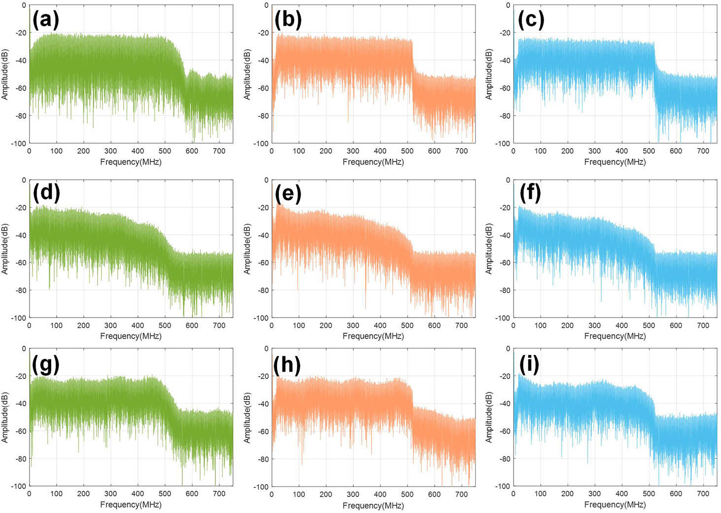
Fig. 6. Spectrum maps for the UVLC system at the transmitter, at the receiver, and after the first post-equalization: (a) CAP at the transmitter; (b) DFT-S OFDM at the transmitter; (c) OFDM at the transmitter; (d) CAP at the receiver; (e) DFT-S OFDM at the receiver; (f) OFDM at the receiver; (g) CAP after the first post-equalization; (h) DFT-S OFDM after the first post-equalization; and (i) OFDM after the first post-equalization.

下载图片 查看所有图片

When considering the main source of nonlinearity in UVLC compared to traditional VLC, we focus on the effect of water. As a result, the comparison of three formats in both the UVLC and VLC systems has been investigated. The performance results are shown in Figs. 710.
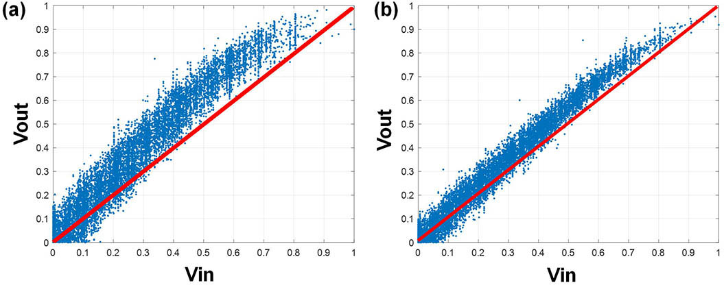
Fig. 7. Amplitude to amplitude (AM/AM) response of CAP modulation in (a) the UVLC system and (b) the VLC system.

下载图片 查看所有图片

The latest expression of the underwater channel only takes optical pass loss into consideration[40,41]. The real underwater VLC channel includes the frequency response of electronic devices (signal amplifier, pre-equalizer, LED driver, LED, etc.) and an optical channel. For the whole UVLC system, the expression of the underwater channel includes the transmitter, the underwater channel and the receiver. The nonlinearity in the UVLC system that arose from the LED, the transmitter driving circuits, PIN photodetector, and the receiver amplification circuits may introduce extra nonlinear noise and can cause detrimental effects to the signal reception. Therefore, it is an essential issue to measure the statistic characteristics of the nonlinear response of the whole UVLC system to achieve a better system performance.

In order to make a good evaluation of the nonlinearities that exist in UVLC and VLC, an amplitude to amplitude (AM/AM) response of CAP modulation was introduced in Ref. [42] in UVLC and the VLC system has been measured in Fig. 7. The signal Vpp is 1.4 V, the LED current is 170 mA, and the LED bias voltage is 3.15 V. The curve is measured by utilizing a narrowband CAP signal whose carrier frequency is at 100 MHz and the bandwidth of the signal is 5 MHz. Figure 7(a) is the results in the UVLC system while Fig. 7(b) is in a VLC system. It can be found clearly that nonlinearity in the UVLC system is higher than in the VLC system. What is more, the variance of the signal distribution in UVLC is larger than in VLC, indicating the SNR degradation.

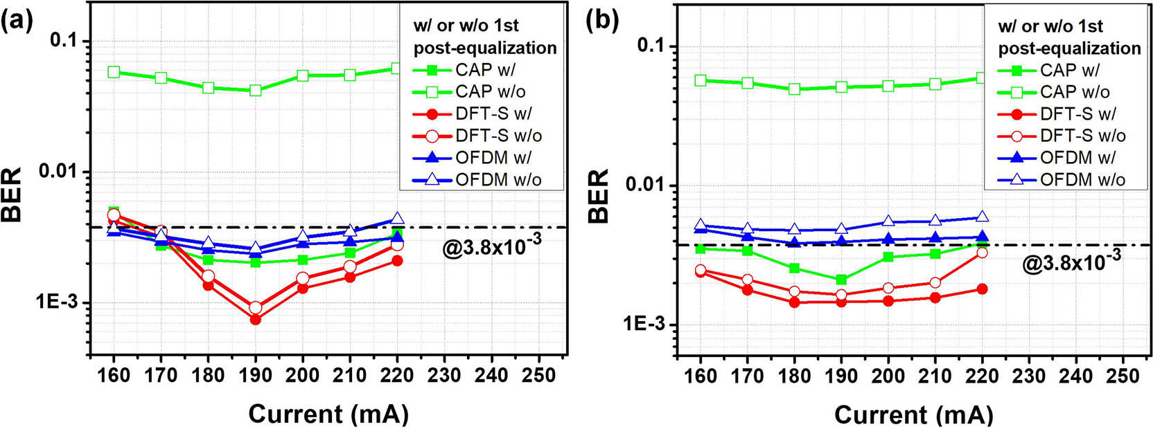
Figure 8 shows the BER performance versus LED current with or without first post-equalization in the traditional VLC system and the UVLC system. It can be seen that both a relatively higher LED current larger than 200 mA, which induces more nonlinear effect, and a relatively lower LED current below 180 mA, which has a low SNR, will deteriorate the BER performance. For three advanced modulation formats, the first-stage post-equalization can improve the BER performance. The performance improvement caused by nonlinear equalization compensation is more obvious at a higher LED current. This is because the nonlinear effects of LEDs dominate mainly at a high LED current, while noise in signals at a low current is a major factor affecting signal quality.

Fig. 8. BER versus LED current in (a) the traditional VLC system and (b) the UVLC system.

下载图片 查看所有图片

What is more, when comparing the experimental results between VLC and UVLC, the performance improvement caused by the first post-equalization is larger in the UVLC system. It is further explained that the nonlinearity effect is larger in the UVLC system, and for three modulation formats, the BER performance in VLC outperforms in UVLC. This can be explained by the fact that since the attenuation of water is relatively large, the SNR of the receiver decreases, so the BER is deteriorated. But for the acceptable operating range of LED current, we found that the operating range in UVLC is larger than in VLC. That is because when current increases, the optical power of the VLC system will increase very fast. The large optical power will soon saturate the receiver and result in failure detection. So in the case of large bias current, the BER in free-space deteriorates faster than underwater.

Regarding the performance improvement of three different modulation formats, CAP modulation presents a larger enhancement than the other two. The optimization for OFDM and DFT-S OFDM is relatively smaller than for CAP, which can be explained that for these two modulation formats, the major nonlinear equalization compensation is conducted by the second post-equalization (i.e., Z-F equalization). The impact of the second post-equalization for these two formats will be analyzed in Fig. 11. Here, the parameters of the first post-equalization are set so that the order of Volterra is 2 and the number of taps of RLS is 9. As for CAP, whose second post-equalization is also RLS-Volterra, the parameters are set so that the order of Volterra is 2 and the number of taps of RLS is 43.

For a nonlinear system, we can use the Volterra series for characterization and use it for nonlinear compensation[15,16]. To get a further elaboration of the degree of nonlinearity in the VLC and the UVLC systems, we also compare the performance of three advanced modulation formats using Volterra for nonlinear compensation. We investigate the effect of the order of Volterra in the first post-equalization. When the order of Volterra is changed, the number of taps of RLS needs to be modified correspondingly to get an optimal BER value. The results are shown in Fig. 9. The working point is chosen at 1 V Vpp, 190 mA current for both the UVLC and VLC systems. We can also see that BER in the VLC system is better than in the UVLC system. The BER performance decreases as the order of Volterra increases. When the Volterra series is further increased, the BER performance tends to be flat. From the figure, we can find that the inflection point of the Volterra series is 2. For the UVLC system, it is necessary to consider more than 3 orders of the Volterra series. For our following experiment, the order of Volterra is set as 2 when taking both the BER performance and computational complexity into consideration.

Fig. 9. BER versus order of Volterra in the UVLC and VLC systems with (a) CAP, (b) DFT-S, and (c) OFDM.

下载图片 查看所有图片

It indicates that besides the signal-to-signal beating interference (SSBI) and beat interference between signals, there is a certain 3-order nonlinear effect, including the cross-interference term among the three signals, the square term of the signals, and cross-interference of other signals. The BER performance in the UVLC system is higher than in the VLC system. These show clearly that in the UVLC system the nonlinearity is more severe than in the traditional VLC system. Experimental results show that the VLC system can achieve lower BER at the same transmission rate, and the UVLC system has more severe nonlinearity compared to a free-space channel. Also, the DFT-S OFDM modulation format performs better in either the UVLC or VLC system.

Since nonlinearity would cause greater ISI, we also discuss the comparison of the number of taps for three formats in the UVLC and the VLC systems. Figure 10 shows the BER versus number of taps in UVLC and VLC systems for three formats. The working point is also at 1 V Vpp, 190 mA current. The BER in UVLC system is higher than in the VLC system. From the figure, we can find that optimal taps number is 9 for UVLC system and 5 for VLC system. The number of taps required for UVLC system is higher than for the VLC system. It shows that ISI induced by nonlinearity increases, and the current bit and adjacent bits have a deeper range of influence.

Fig. 10. BER versus number of taps in the UVLC and VLC systems with (a) CAP, (b) DFT-S, and (c) OFDM.

下载图片 查看所有图片

The comparison between the UVLC system and the traditional VLC system has been studied in Figs. 710. All the experimental results show that UVLC has higher nonlinearity compared to the VLC system. Next, we focus on the performance of three advanced modulation formats in the UVLC system.

We compared the BER performance using sparse pilot to do linear interpolation for channel equalization and found that the performance would deteriorate. The results are shown in Fig. 11. Figure 11(a) shows the BER performance with different numbers of pilot. Figures 11(b) and 11(c) show the channel curve estimated by linear Z-F (number of pilot=2) and nonlinear Z-F (number of pilot=256). It shows that the minimum number of pilot for the second post-equalization is 32. At the same time, it means that the Z-F method compensates nonlinearity for OFDM and DFT-S OFDM. Therefore, nonlinearity compensation is still very necessary for OFDM and DFT-S OFDM modulation formats. But the main gain is obtained by applying second nonlinear post-equalization. The combination of two-level post-equalization (i.e., RLS-Volterra and Z-F) will optimize the system performance better.
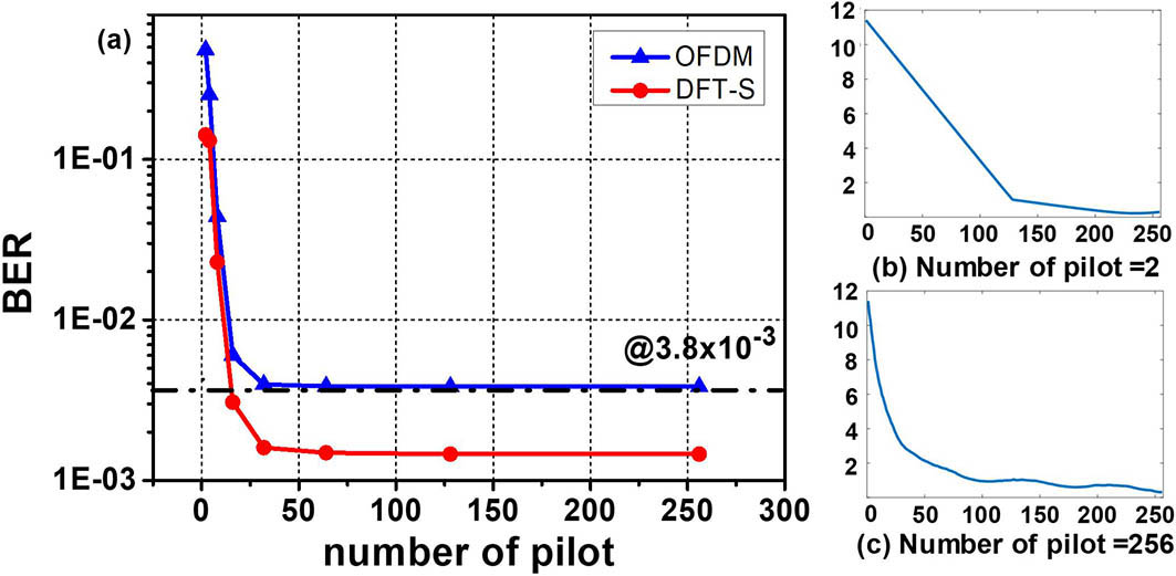
Fig. 11. BER performance of the 2nd post-equalization for OFDM and DFT-S OFDM in the UVLC system: (a) with different number of pilot, (b) channel curve when the number of pilot is 2, and (c) channel curve when the number of pilot is 256.

下载图片 查看所有图片

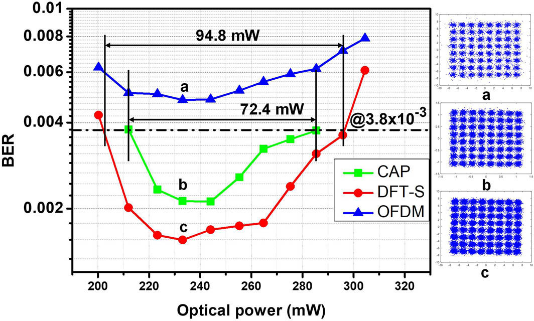
We compare the BER performance under different LED optical power in the UVLC system. The results are shown in Fig. 12. From the figure, only CAP and DFT-S can achieve the HD-FEC threshold, and the dynamic range for CAP is 72.4 mW while for DFT-S it is 94.8 mW. DFT-S achieves a broadening of 22.4 mW in the dynamic range for optical power. The inset figures are the constellation diagrams. They show clearly that DFT-S performs the best.

Fig. 12. BER versus LED optical power of CAP, DFT-S, and OFDM systems.

下载图片 查看所有图片

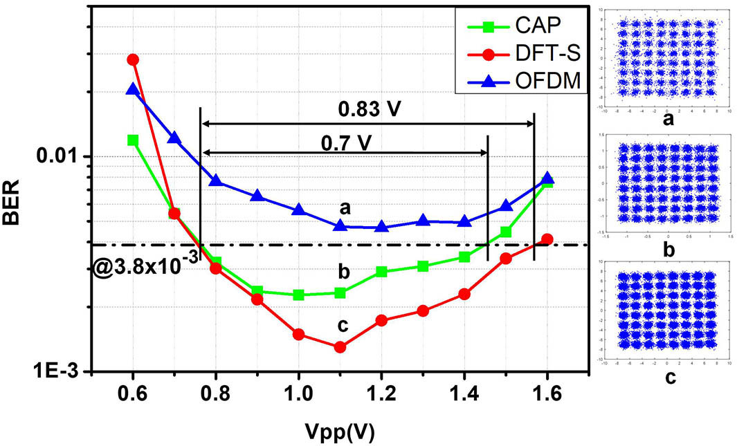
Figure 13 shows the BER versus peak-to-peak voltages of the LED in the CAP, DFT-S OFDM, and OFDM systems. Under the HD-FEC, the dynamic range of CAP is 0.7 V and the dynamic range of DFT-S is 0.83 V. Compared to the CAP modulation format, the enlargement of 0.13 V in Vpp is successfully realized by applying the DFT-S modulation format. It means that DFT-S modulation format allows the system’s BER to stay below the HD-FEC threshold in a wider range of Vpp, thus improving the system stability.

Fig. 13. BER versus peak-to-peak voltages (Vpp) of the LED in CAP, DFT-S OFDM, and OFDM systems.

下载图片 查看所有图片

To investigate the influence of bandwidth, Fig. 14 shows the BER performance versus bandwidth in the UVLC system. It can be found that when the bandwidth is less than 550 MHz the DFT-S OFDM modulation format performs best. It is worth noting that since the DFT-S OFDM is a single-carrier scheme, it is more sensitive to the ISI. Therefore, DFT-S OFDM cannot outperform all the time. When the bandwidth increases up to 560 MHz (i.e., the ISI influence is more severe), the DFT-S OFDM format performs worst. However, the OFDM has the lowest BER at 560 MHz.
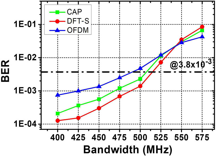
Fig. 14. BER performance versus bandwidth of three advanced modulation formats in the UVLC system.

下载图片 查看所有图片

In this paper, a comprehensive comparison is presented among CAP-64, OFDM 64QAM, and DFT-S OFDM 64QAM with the RLS-Volterra post-equalizer in an UVLC system and traditional VLC system. We present a two-level hybrid post-equalizer to compare against both the linear distortion and nonlinear distortion. The first post-equalization is based on a novel RLS-Volterra. The performance improvement created by the first post-equalization is larger in the UVLC system compared to that in the VLC system. The UVLC system has a more severe nonlinearity than the traditional VLC system. The comparison is carried out to evaluate the performance of each modulation format in terms of PAPR, LED current, nonlinear equalization, optical power, and peak-to-peak voltage. A transmitting rate of 3.0 Gb/s over 1.2 m underwater VLC transmission is easily achieved by CAP-64 and DFT-S OFDM 64QAM. From the experimental results, DFT-S OFDM outperforms both the CAP and OFDM signals. It shows that DFT-S OFDM is a potential candidate in the future underwater VLC system.

References

[1] 1NakajimaA.SakoN.KamemuraM.WakayamaY.FukuzawaA.SugiyamaH.OkadaN., in Proceedings of the International Conference on Space Optical Systems and Applications (2012), p. 12.

[2] 2Le MinhH.O’BrienD.FaulknerG.ZengL.LeeK.JungD.OhY., IEEE Photon. Technol. Lett.20, 1243 (2008).IPTLEL1041-113510.1109/LPT.2008.926030

[3] 3Le MinhH.O’BrienD.FaulknerG.ZengL.LeeK.JungD.OhY., in Proceedings of the European Conference on Optical Communication ECOC (2008), p. 1.

[4] 4GruborJ.RandelS.LangerK. D.WalewskiJ. W., in Proceedings of 6th International Symposium on Communication Systems, Networks and Digital Signal Processing CNSDSP (2008) p. 165.

[5] 5VucicJ.KottkeC.NerreterS.BüttnerA.LangerK.-D.WalewskiJ. W., IEEE Photon. Technol. Lett.21, 1511 (2009).10.1109/LPT.2009.2028696

[6] 6VucicJ.KottkeC.NerreterS.LangerK.-D.WalewskiJ. W., J. Lightwave Technol.28, 3512 (2010).JLTEDG0733-8724

[7] 7VucicJ.KottkeC.HabelK.LangerK.-D., in Proceedings of Optical Fiber Communication Conference (2011), paper OWB6.

[8] 8KottkeC.HiltJ.HabelK.VučićJ.LangerK.-D., in Proceedings of European Conference on Optical Communication ECOC (2012), paper We.3.B.4.

[9] 9CossuG.KhalidA. M.ChoudhuryP.CorsiniR.CiaramellaE., in Proceedings of European Conference on Optical Communication ECOC (2012), paper P4. 16.

[10] 10CossuG.KhalidA. M.ChoudhuryP.CorsiniR.CiaramellaE., Opt. Express20, B501 (2012).OPEXFF1094-408710.1364/OE.20.00B501

[11] 11WuF.-M.LinC.-T.WeiC.-C.ChenC.-W.HuangH.-T.HoC.-H., IEEE Photon. Technol. Lett.24, 1730 (2012).IPTLEL1041-113510.1109/LPT.2012.2210540

[12] 12WuF.-M.LinC.-T.WeiC.-C.ChenC.-W.ChenZ.-Y.HuangK., in Proceedings of Optical Fiber Communication Conference OFC (2013), paper OTh1G.4.

[13] 13CossuG.WajahatA.CorsiniR.CiaramellaE., in Proceedings of European Conference on Optical Communication ECOC (2014), paper We.3.6.4.

[14] 14WangY.HuangX.ZhangJ.WangY.ChiN., Opt. Express22, 15328 (2014).OPEXFF1094-408710.1364/OE.22.015328

[15] 15WangY.HuangX.TaoL.ShiJ.ChiN., Opt. Express23, 13626 (2015).OPEXFF1094-408710.1364/OE.23.013626

[16] 16WangY.TaoL.HuangX.ShiJ.ChiN., IEEE Photon. J.7, 7904507 (2015).

[17] 17LiX.BamiedakisN.GuoX.McKendryJ. J. D.XieE.FerreiraR.GuE.DawsonM. D.PentyR. V.WhiteI. H., in Proceedings of European Conference on Optical Communication ECOC (2015), paper 0640.

[18] 18ChiN.ZhangM.ZhouY.ZhaoJ., Opt. Express24, 21663 (2016).OPEXFF1094-408710.1364/OE.24.021663

[19] 19ChiN.ShiJ.ZhouY.WangY.ZhangJ.HuangX., in Proceedings of Photonics Society Summer Topical Meeting Series (2016), p. 4.

[20] 20ChunH.RajbhandariS.FaulknerG.TsonevD.XieE.McKendryK.GuE.DawsonM.O’BrienD.HassH., J. Lightwave Technol.34, 3047 (2016).JLTEDG0733-872410.1109/JLT.2016.2554145

[21] 21ZhuX.WangF.ShiM.ChiN.LiuJ.JiangF., in Proceedings of Optical Fiber Communications Conference and Exhibition (2018), paper M3K.3.

[22] 22ChiN.HaasH.KavehradM.LittleT. D. C.HuangX., in Proceedings of IEEE Wireless Communications (2015), p. 5.

[23] 23WangY.WangY.ChiN.YuJ.ShangH., Opt. Express21, 1203 (2013).OPEXFF1094-408710.1364/OE.21.001203

[24] 24WangZ.ZhangM.ChenS.ChiN., Chin. Opt. Lett.15, 030602 (2017).CJOEE31671-7694

[25] 25ShiM.WangF.ZhangM.WangZ.ChiN., in Proceedings of IEEE International Conference on Communications Workshops (2017), p. 337.

[26] 26QianH.YaoS. J.CaiS. Z.ZhouT., IEEE Photon. J.6, 7901508 (2014).10.1109/JPHOT.2014.2331242

[27] 27WangC.YuH.ZhuY., IEEE Photon. J.8, 7906311 (2017).

[28] 28WangY.TaoL.HuangX.ShiJ.ChiN., IEEE Photon. J.7, 7907907 (2015).

[29] 29TaoL.TanH.FangC.ChiN., in IEEE Progress in Electromagnetic Research Symposium (2016), p. 4863.

[30] 30OubeiH. M.ShenC.KammounA.ZediniE.ParkK.SunX.LiuG.KangC. H.NgT. K.AlouiniM.OoiB. S., Jpn. J. Appl. Phys.57, 08PA06 (2018).10.7567/JJAP.57.08PA06

[31] 31KongM.ChenY.SarwarR.SunB.XuZ.HanJ.ChenJ.QinH.XuJ., Opt. Express26, 3087 (2018).OPEXFF1094-408710.1364/OE.26.003087

[32] 32WangF.LiuY.JiangF.ChiN., Opt. Commun.425, 106 (2018).OPCOB80030-401810.1016/j.optcom.2018.04.073

[33] 33ZhangD. F.ZhuY. J.WangT.TianZ. J.ZhangY. Y., Appl. Mech. Mater.511–512, 357 (2014).10.4028/www.scientific.net/AMM.511-512

[34] 34DoniecM.VasilescuI.ChitreM.DetweilerC.Hoffmann-KuhntM.RusD., in Oceans IEEE Conference (2010), p. 1.

[35] 35CossuG.CorsiniR.KhalidA. M.BalestrinoS.CoppelliA.CaitiA.CiaramellaE., in International Workshop on Optical Wireless Communications Conference (2014), p. 11.

[36] 36XuJ.KongM.LinA.SongY.YuX.QuF.HanJ.DengN., Opt. Commun.369, 100 (2016).OPCOB80030-401810.1016/j.optcom.2016.02.044

[37] 37TianP.LiuX.YiS.HuangY.ZhangS.ZhouX.HuL.ZhengL.LiuR., Opt. Express25, 1193 (2017).OPEXFF1094-408710.1364/OE.25.001193

[38] 38StepniakG.SiuzdakJ.ZwierkoP., IEEE Photon. Technol. Lett.25, 1597 (2013).IPTLEL1041-113510.1109/LPT.2013.2272511

[39] 39DaumontS.BaselR.LouetY., in 3rd International Symposium on Communications, Control and Signal Processing (2008), p. 841.

[40] 40ElamassieM.MiramirkhaniF.UysalM., in IEEE International Conference on Communications Workshops (2018), p. 1.

[41] 41MinhH. L.O’BrienD.FaulknerG.ZengL.LeeK.JungD.OhY.WonE. T., IEEE Photon. Technol. Lett.21, 1063 (2009).IPTLEL1041-113510.1109/LPT.2009.2022413

[42] 42ZhouY.WangC.ZhangJ.ZhaoJ.ZengM.ChiN., in Optical Fiber Communications Conference and Exhibition (2017), paper W2A.40.

Nan Chi, Meng Shi. Advanced modulation formats for underwater visible light communications [Invited][J]. Chinese Optics Letters, 2018, 16(12): 120603.

本文已被 3 篇论文引用
被引统计数据来源于中国光学期刊网
引用该论文: TXT   |   EndNote

相关论文

加载中...

关于本站 Cookie 的使用提示

中国光学期刊网使用基于 cookie 的技术来更好地为您提供各项服务,点击此处了解我们的隐私策略。 如您需继续使用本网站,请您授权我们使用本地 cookie 来保存部分信息。
全站搜索
您最值得信赖的光电行业旗舰网络服务平台!