Photonics Research, 2016, 4 (2): 02000084, Published Online: Sep. 28, 2016
Design of a single all-silicon ring resonator with a 150 nm free spectral range and a 100 nm tuning range around 1550 nm  Download: 921次
Figures & Tables
Fig. 1. Schematic of the tCMT model for ring resonators. (a) In an ideal ring resonator with no reflection inside, only one circulating mode is activated. (b) In a ring resonator with internal backreflection, the two modes are coupled and thus simultaneously active.
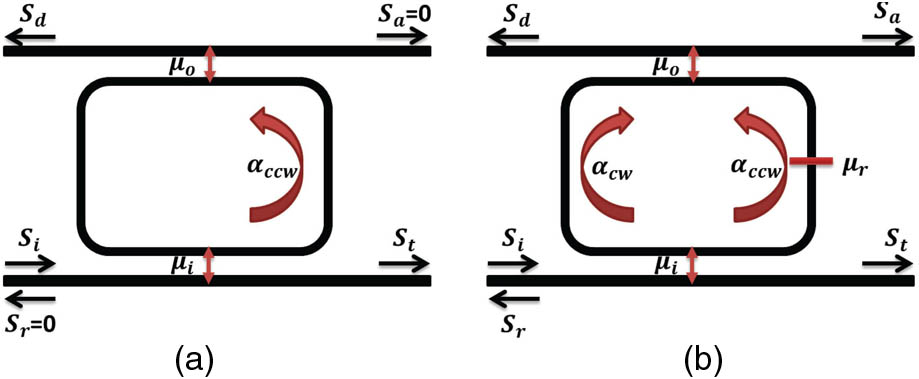
Fig. 2. At the critical coupling point, the extinction ratio drops dramatically with increasing reflection until it reaches an almost constant value.

Fig. 3. Extinction ratio still changes significantly with increasing reflectivity when the MRR is configured as κ i = κ o

Fig. 4. These figures show how the extinction ratio as well as the side mode suppression changes with power coupling coefficient when the MRR is designed as κ i = κ o

Fig. 5. The ring resonator has a loop MZI tunable reflector inside, which introduces a wavelength-dependent intentional reflection that couples two circulating modes.

Fig. 6. Curves of the reflection spectra of the reflector. The directional couplers are designed to be a 50/50 splitter. (a) The directional coupler performance is wavelength independent. (b) A linear model for directional coupler extracted from FDTD simulation is added.

Fig. 7. Simulated throughport of our device. The order m κ i 2 = κ o 2

Fig. 8. In common tuning configuration, the zero-reflection wavelength of the reflector and the resonance wavelength of the MRR shift at the same rate, and thus the MRR remains single mode. (a) The shift of the zero-reflection wavelength of the MZI based reflector induced by effective index n eff change. (b) The shift of the resonance wavelength of the MRR induced by effective index n eff change.

Fig. 9. Instead of using one common phase shifter, we can implement two separate phase shifters to achieve individual tuning of the zero-reflection wavelength of the reflector and the resonance wavelength of the ring.

Fig. 10. Two phase shifters are implemented, with PS1 responsible for the mode selection and PS2 in charge of comb tuning. With the same index change, we achieve a 4 times larger wavelength shift compared to common tuning. (a) Without PS2, the single mode resonance can only take place at some discrete wavelength points, as the zero-reflection wavelength of the reflector might not match the resonance of the ring. (b) With PS2 working, the single mode resonance can be tuned continuously, as the resonance of the ring resonator can now be aligned to the zero-reflection wavelength of the reflector.

Fig. 11. When optimizing for a larger tuning range (at the cost of smaller SMSR) we achieve a tuning range almost as wide as 100 nm with the same index change.

Fig. 12. Tuning maps for the two phase shifters PS1 and PS2 to achieve a continuous shift of the single mode resonance. (a), (c), and (e) give the results of the first design, where the SMSR of each wavelength is larger than 28 dB while the tuning range is only 30 nm, 4 times wider than that of a normal silicon ring resonator. The results of the modified design are illustrated in (b), (d), and (f) where the design parameters are changed to achieve a much wider tuning range around 90 nm at the price of a smaller SMSR, but still, at each wavelength, a SMSR larger than 14 dB can be guaranteed. (a) Wavelength of single mode ring 1. (b) Wavelength of single mode ring 2. (c) Extinction ratio of single mode ring 1. (d) Extinction ratio of single mode ring 2. (e) Side mode suppression of single mode ring 1. (f) Side mode suppression of single mode ring 2.


Ang Li, Qiangsheng Huang, Wim Bogaerts. Design of a single all-silicon ring resonator with a 150 nm free spectral range and a 100 nm tuning range around 1550 nm[J]. Photonics Research, 2016, 4(2): 02000084.


 PDF全文
PDF全文

