Chinese Optics Letters, 2019, 17 (8): 080501, Published Online: Jul. 23, 2019  

Multi-band imaging and focusing of photonic crystal flat lens with scatterer-size gradient Download: 911次

Author Affiliations
Key Laboratory for Micro/Nano Optoelectronic Devices of Ministry of Education & Hunan Provincial Key Laboratory of Low-Dimensional Structural Physics and Devices, School of Physics and Electronics, Hunan University, Changsha 410082, China
Abstract
In this Letter, a photonic crystal (PC) flat lens with a scatterer-size gradient is proposed, which simultaneously achieves imaging of the point source and sub-wavelength focusing of the plane wave in the first, second, and fifth bands. The imaging of the point source breaks through the diffraction limit in the second and fifth bands. The PC flat lens with the scatterer-size gradient is expected to be used in a new multifunctional optical imaging and focusing device, which improves the application potential of a PC flat lens.

A photonic crystal (PC)[13" target="_self" style="display: inline;">–3] is a kind of artificial microstructure material whose dielectric constant is arranged according to certain regularity, including a periodic PC (PPC) and a quasi-PPC (QPC). Because of its controllable photon motion, researchers have been very interested in it and have conducted extensive and in-depth research on its properties and applications, especially in micro–nano photon devices, including fibers[410" target="_self" style="display: inline;">10], lasers[11,12], filters[13,14], waveguides[15,16], prisms[17,18], lenses[1928" target="_self" style="display: inline;">28], etc.

A PC has special band structures, which can realize negative refraction in some specific bands[19,20]. Previous works have shown that a common PC (CPC) flat lens can achieve imaging of the point source[20,21], but it cannot achieve focusing of the plane wave. The PC flat lens with a scatterer-size gradient can achieve imaging of the point source[23] and focusing of the plane wave[24,25], but the band is single in previous works. The PC flat lens with a scatterer-refractive-index gradient can achieve multi-band super-resolution imaging of the point source[28], but the plane wave can only be focused in a single and low band. If the imaging of the point source and the focusing of the plane wave are simultaneously achieved in the multi-band, not only are the advantages of each band fully utilized, but also it is of great significance to design new optical focusing and imaging devices, reduce the size of devices, reduce the complexity of the system, introduce new optical functions, and so on.

In this Letter, a PC flat lens with a scatterer-size gradient is proposed, which can simultaneously achieve imaging of the point source and focusing of the plane wave in the multi-band.

The model of the two-dimensional (2D) triangular lattice PC flat lens with a scatterer-size gradient is shown in Fig. 1.

Fig. 1. Model of the PC flat lens with a scatterer-size gradient; the red arrow represents the light path of plane wave focusing, and the black arrow represents the light path of point source imaging.

下载图片 查看所有图片

When the photonic band gap (PBG) exists, the PC, whose equi-frequency line (EFL) is a circle or approximately a circle, can be equivalent to a uniform medium[29]. In addition, the PBG is generated easier by larger refractive index differences in the PC. Therefore, the scatterer (dielectric column) material is set as germanium (εr=16) with a high refractive index, and the background material is set as air in this Letter. The lattice constant a=1μm remains unchanged throughout the lens, the width w=(203+0.4)a, the thickness d=9.8a, and the fixed object distance u=d/2=4.9a. The scatterer’s radius has gradient in the ±Y-axis directions, unchanged in the X-axis direction, and the scatterer’s radius in the middlemost row is r0=0.4a. In the ±Y-axis directions, the scatterer’s radius of the ith row from the middlemost row to the two sides is ri=r00.01×i. The image distance and the focal length are v1=x1d/2, v2=x2d/2, and x1, x2, are the positions of the image and focus, respectively. The sum of the object distance and image distance is duv=u+v1=x1.

The theory of negative refraction of the PC is to produce a “negative group refractive index” by using a special dispersion relation of PCs at the edge of the band gap[30]. When the lightwave is incident on the PC from air, the refractive direction is determined by the group velocity, and the vector relationship between the group velocity and wave vector k is[29]vg=kω(k).

Because the frequency variation trend in the EFL of the band is correlated with its band structure, the dispersion curve can be used to judge whether the PC has a negative refraction effect. If the EFL shape of the band is circular, the PC is approximately a homogeneous isotropic medium, and the group velocity is collinear with the wave vector. The refractive direction of the beam in the PC can be analyzed using the EFL method[29], as shown in Fig. 2.

Fig. 2. Direction of beam propagation in the PC is analyzed by the EFL method[29]. The left picture shows the EFL of air corresponding to the frequency of the incident beam, indicating that the beam is incident on the PC from the air. The right picture shows the EFL of the band corresponding to the frequency of the refractive beam, indicating the direction of propagation of the beam in the PC[28]. This is just a schematic diagram.

下载图片 查看所有图片

As shown in Fig. 2, if the frequency gradually decreases from the center to the radially outward direction, the refraction direction is vg1. At this time, the incident and refractive beams are on the same side of normal, and it is known from the theory of negative refraction that vg1 is the direction of negative refraction.

All simulation calculations in TM polarization mode are performed with COMSOL Multiphysics software based on the finite element method (FEM). Since the scatterer’s radius of the PC flat lens with a scatterer-size gradient does not change periodically, the band structure of the PC flat lens with the scatterer-size gradient cannot be directly calculated. Therefore, the band structures of two CPCs with the scatterer’s radius r=0.40μm and r=0.39μm are, respectively, calculated, as shown in Fig. 3(a). The EFLs of the first band of three CPCs with different scatterer’s radii are shown in Fig. 3(b). The effect of different scatterer radii on the effective refractive index (ERI) is shown in Fig. 3(c). The influence[22,31] of different scatterer radii on group velocity is shown in Fig. 3(d) schematically.

Fig. 3. (a) Band structures of two CPCs with the scatterer radius r=0.40μm and r=0.39μm (the two radii correspond to the band structures that are, respectively, distinguished by solid and dotted lines). EM propagates along the ΓK direction of the irreducible Brillouin zone. (b) EFLs of the first band of three CPCs with different scatterer radii, the scatterer radii of the CPC are 0.4 μm (black), 0.3 μm (red), and 0.2 μm (blue), respectively; (c) ERI of the first band of CPC with different scatterer radii; (d) influence of different scatterer radii on group velocity[31]. This is just a schematic diagram.

下载图片 查看所有图片

From Fig. 3(a), it can be seen that the shape of the corresponding band structures for two CPCs with the scatterer’s radius r=0.40μm and r=0.39μm does not change much. It can be seen from Fig. 3(b) that, as the scatterer’s radius of CPC decreases, the EFL of the first band gradually approaches the center of the light cone, which is similar to previous works[24,25]. Therefore, the PC flat lens with a scatterer-size gradient can achieve focusing of the plane wave in this Letter. Since the EFLs of the first band of the CPC are approximately circular, the ERI of the first band can be calculated according to the ratio of the radius of the EFL to the radius of the light cone[29]. As can be seen from Fig. 3(c), the ERI of the first band increases as the radius of the scatterer increases. It can be seen from previous works[32,33] that the imaging mechanism of the PC flat lens in the second and fifth bands is a negative refraction effect. The negative ERI of the second and fifth bands of the CPC varies with the change of the scatterer’s radius. Therefore, when the light beam is incident on the PC flat lens with the scatterer-size gradient, the trajectory of the beam propagation is curved due to the difference of the negative ERI of the second and fifth bands in different layers, as shown in Fig. 3(d). In addition, the imaging mechanism of the PC flat lens in the first band is the plane wave approximation, so Fig. 3(d) is not suitable for the first band.

Theoretical analysis of Fig. 3(b) shows that the PC flat lens with a scatterer-size gradient can achieve focusing of the plane wave in the first band. From a large number of simulation calculations, the focusing frequency f1 is in the range of [0.153, 0.157] (only part of the first band), and the focusing wavelength λ1 is in the range of [6.383 μm, 6.535 μm] (f1=a/λ1) in the first band. It is known from previous work[28] that the beam excited by the point source traverses the middle five rows of scatterers of the PC flat lens at the incident plane. Figure 1 shows that the intercept length of the middle five rows of scatterers is L=4ΓM=23·a, so λ1·uL2, which satisfies the far-field condition of the spherical wave. Therefore, the PC flat lens with a scatterer-size gradient can achieve imaging of the point source in the first band. Taking λ1=6.522μm as an example, the imaging and focusing characteristics of the PC flat lens with a scatterer-size gradient in the first band are shown in Fig. 4.

Fig. 4. Take λ1=6.522μm as an example: (a) the imaging field of the gradient PC flat lens when the incident beam is the point source (PS) lightwave; (b) the focusing field of the gradient PC flat lens when the incident beam is a plane wave (PW); (c) field power (normalized) of imaging of PS and focusing of PW in the axial plane; (d) field power (normalized) of imaging of PS in the imaging plane and focusing of PW in the focusing plane.

下载图片 查看所有图片

As can be seen from Figs. 4(a) and 4(b), when the wavelength of the incident beam belongs to the focusing wavelength range, the imaging of the point source and the focusing of the plane wave can be realized by the PC flat lens. Through the data analysis, the image distance and focal length are v1=3.90μm and v2=4.72μm, respectively, as shown in Fig. 4(c), and the sum of the object distance and image distance is duv=8.80μm, which is less than the lens thickness. From Fig. 4(d), it can be seen that FWHMPS=0.629λ and FWHMPW=0.342λ, which show that the PC flat lens with a scatterer-size gradient can simultaneously realize imaging of the point source and sub-wavelength focusing of the plane wave in the first band.

It can be known from previous work[32] that the CPC flat lens can realize imaging of the point source in the second band, and the imaging mechanism is that the CPC flat lens has negative ERI in the second band. As shown in Fig. 3(a), when the scatterer’s radius changes, the second band changes slightly, so it can be speculated that the PC flat lens with a scatterer-size gradient can achieve imaging of the point source in the second band. From a large number of simulation calculations, the focusing frequency f2 is in the range of [0.241, 0.242] (only a part of the second band), and the focusing wavelength λ2 is in the range of [4.127 μm, 4.184 μm] (f2=a/λ2) in the second band. Taking λ2=4.127μm as an example, the imaging and focusing characteristics of the PC flat lens with a scatterer-size gradient in the second band are shown in Fig. 5.

Fig. 5. Take λ2=4.127μm as an example: (a) the imaging field of the CPC flat lens with r=0.40μm when the incident beam is the PS lightwave; (b) the imaging field of the gradient PC flat lens when the incident beam is the PS lightwave; (c) the focusing field of the gradient PC flat lens when the incident beam is the PW; (d) field power (normalized) of imaging of the PS and focusing of the PW in the axial plane; (e) field power (normalized) of imaging of the PS in the imaging plane and focusing of the PW in the focusing plane; (f) the second band EFLs of two CPCs with scatterer radius r=0.40μm and r=0.39μm (the EFLs corresponding to the two radii and the light cone are distinguished by black, purple, and blue). The blue arrow is the incident beam, which is incident from the air to the PC. The red arrow is the direction of propagation of the beam in the PC, that is, the refractive beam. This is just a schematic diagram[34].

下载图片 查看所有图片

As shown in Figs. 5(b) and 5(c), the PC flat lens with a scatterer-size gradient can realize imaging of the point source and focusing of the plane wave within the focusing wavelength range. It is shown from Fig. 5(d) that the image distance and focal length are v1=3.52μm and v2=3.72μm, respectively, and the sum of the object distance and image distance is duv=8.42μm, which is greater than the lens thickness. From Fig. 5(e), it can be seen that FWHMPS=0.425λ and FWHMPW=0.445λ. From Fig. 5(f), it can be seen that the incident and refractive beams are on the same side of the normal, and the shape of the EFL changes slightly as the scatterer radius changes, so the PC flat lens with a scatterer-size gradient has a negative refraction effect. Therefore, the PC flat lens with a scatterer-size gradient can realize imaging of the point source in the second band. As can be seen from Fig. 5(f), as the scatterer’s radius of the CPC increases, the corresponding second band EFL gradually approaches the center of the light cone, which is similar to previous works[24,25]. Therefore, the PC flat lens with a scatterer-size gradient can achieve focusing of the plane wave in the second band. In summary, the PC flat lens with a scatterer-size gradient simultaneously achieves super-resolution imaging of the point source and sub-wavelength focusing of the plane wave in the second band. In addition, when λ2=4.127μm, the image distance in CPC flat lens imaging is vCPC=1.77μm, and FWHMCPC=0.612λ, which show that the CPC flat lens cannot achieve super-resolution imaging of the point source, as shown in Figs. 5(a), 5(d), 5(e).

From the anisotropic left-hand negative refraction theory[33], it can be found that the fifth band has a negative refraction effect, and its focusing frequency f5 is in the range of [0.385, 0.387] (only a part of the fifth band); then, the focusing wavelength λ5 is in the range of [2.582 μm, 2.595 μm] (f5=a/λ5) in the fifth band. Taking λ5=2.582μm as an example, the imaging and focusing characteristics of the PC flat lens with a scatterer-size gradient is in the fifth band, as shown in Fig. 6.

Fig. 6. Take λ5=2.582μm as an example: (a) the imaging field of the CPC flat lens with r=0.40μm when the incident beam is the PS lightwave; (b) the imaging field of the gradient PC flat lens when the incident beam is the PS lightwave; (c) the focusing field of the gradient PC flat lens when the incident beam is the PW; (d) field power (normalized) of imaging of the PS and focusing of the PW in the axial plane; (e) field power (normalized) of imaging of the PS in the imaging plane and focusing of the PW in the focusing plane; (f) the fifth band EFLs of two CPCs with scatterer radii r=0.40μm and r=0.39μm (the EFLs corresponding to the two radii and the light cone are distinguished by black, purple, and blue). The blue arrow is the incident beam, which is incident from the air to the PC. The red arrow is the direction of propagation of the beam in the PC, that is, the refractive beam. This is just a schematic diagram[34].

下载图片 查看所有图片

From Figs. 6(b) and 6(c), it can be seen that the PC flat lens with a scatterer-size gradient can simultaneously realize imaging of the point source and focusing of the plane wave in the focusing wavelength range. It is shown from Fig. 6(d) that the image distance and focal length are v1=1.89μm and v2=1.47μm, respectively, and the sum of the object distance and image distance is duv=6.79μm, which is less than the lens thickness. From Fig. 6(e), it can be seen that FWHMPS=0.484λ and FWHMPW=0.447λ. As shown in Fig. 6(f), the fifth band EFL has negative refraction caused by the anisotropic EFL[35], as indicated by the red arrow, and the incident beam and the refractive beam are on the same side of the normal. Therefore, the PC flat lens can achieve imaging of the point source in the fifth band. With the increasing of the scatterer’s radius, the EFL gradually approaches the light cone, which is similar to previous work[25], so the PC flat lens with a scatterer-size gradient can achieve focusing of the plane wave in the fifth band. In summary, the PC flat lens with a scatterer-size gradient simultaneously achieves super-resolution imaging of the point source and sub-wavelength focusing of the plane wave in the fifth band. In addition, when λ5=2.582μm, the image distance in CPC flat lens imaging is vCPC=5.08μm, and FWHMCPC=0.445λ, which show that the CPC flat lens can achieve super-resolution imaging of the point source, as shown in Figs. 6(a), 6(d), and 6(e).

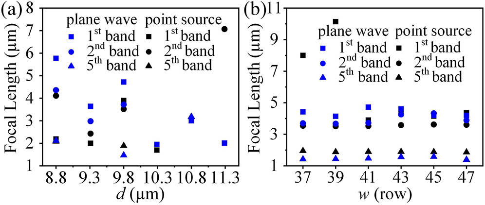
As can be seen from Fig. 7(a), when the lens thickness is set to 9.8 μm, the lens can simultaneously achieve imaging of the point source and focusing of the plane wave in the three bands. As shown in Fig. 7(b), when the lens width is changed, and the incident beam is a point source lightwave, the image distance of the first band changes greatly, and the image distances of the second and fifth bands are substantially unchanged. When the lens width is changed, and the incident beam is a plane wave, the focal length variation of the first band is small, and the focal lengths of the second and fifth bands are substantially unchanged.

Fig. 7. Effect of the thickness and width on the focal length: (a) thickness; (b) width represented by the rows of the scatterers.

下载图片 查看所有图片

In conclusion, the PC flat lens with a scatterer-size gradient can simultaneously achieve imaging of the point source and focusing of the plane wave in the multi-band with only one structure, which is expected to reduce the preparation cost of the optical device and provide a reference for the design of new optical focusing and imaging devices in the future.

References

[1] YablonovitchE., Phys. Rev. Lett.58, 2059 (1987).PRLTAO0031-9007

[2] JohnS., Phys. Rev. Lett.58, 2486 (1987).PRLTAO0031-9007

[3] ChanY. S.ChanC. T.LiuZ. Y., Phys. Rev. Lett.80, 956 (1998).PRLTAO0031-9007

[4] MarkosC.TraversJ. C.AbdolvandA.EggletonB. J.BangO., Rev. Mod. Phys.89, 045003 (2017).

[5] CaiW.LiuE.FengB.XiaoW.LiuH.WangZ.WangS.LiangT.LiuJ.LiuJ., J. Opt. Soc. Am. A33, 2108 (2016).

[6] CaiW.LiuE.FengB.LiuH.WangZ.XiaoW.LiangT.WangS.LiuJ.LiuJ., Optik127, 4438 (2016).

[7] LiuH.XiaoW.CaiW.LiuE.FengB.WangZ.LiangT.WangS.LiuJ., Opt. Eng.55, 036101 (2016).

[8] LiuE.YanB.TanW.XieJ.GeR.LiuJ., Superlattices Microstruct.115, 123 (2018).

[9] LiuE.TanW.YanB.XieJ.GeR.LiuJ., J. Opt. Soc. Am. A35, 431 (2018).

[10] YanB.WangA.LiuE.TanW.XieJ.GeR.LiuJ., J. Phys. D: Appl. Phys.51, 155105 (2018).

[11] VitielloM. S.NobileM.RonzaniA.TredicucciA.CastellanoF.TaloraV.LiL.LinfieldE. H.DaviesA. G., Nat. Commun.5, 5884 (2014).

[12] BakozA. P.LilesA. A.Gonzalez-FernandezA. A.HabrusevaT.HuC.ViktorovE. A.HegartyS. P.FaolainL. O., Light Sci. Appl.7, 39 (2018).

[13] QianQ.XuC.WangC., Sci. Rep.7, 16574 (2017).

[14] ZhaoY.WangZ.JiangZ.ChenX.YueC.WangJ.LiuJ., J. Infrared Millim. Waves36, 342 (2017).

[15] WangZ.SuK.FengB.ZhangT.HuangW.CaiW.XiaoW.LiuH.LiuJ., Chin. Opt. Lett.16, 011301 (2018).

[16] SernaS.ZhangW.HoangT. H. C.Alonso-RamosC.Marris-MoriniD.VivienL.CassanE., Photon. Res.6, 54 (2018).

[17] LiuJ.TanW.LiuE.HuH.FanZ.ZhangT.ZhangX., J. Opt. Soc. Am. A33, 978 (2016).

[18] SpiteriL.MessinaR., Phys. Rev. Lett.119, 155501 (2017).PRLTAO0031-9007

[19] LuoC.JohnsonS. G.JoannopoulosJ. D.PendryJ. B., Phys. Rev. B65, 201104 (2002).

[20] ParimiP. V.LuW. T.VodoP.SridharS., Nature426, 404 (2003).

[21] ZhangX., Phys. Rev. B71, 165116 (2005).

[22] QiW.JohnM. G.WounjhangP., Opt. Express16, 16941 (2008).

[23] ShiP.HuangK.LiY. P., J. Opt. Soc. Am. A28, 2171 (2011).

[24] GaufilletF.AkmansoyE., J. Appl. Phys.114, 083105 (2013).

[25] GaufilletF.AkmansoyE., Opt. Mater.47, 555 (2015).

[26] LiuJ.LiuE.FanZ.ZhangX., Appl. Phys. Express8, 112003 (2015).

[27] LiuJ.FanZ., IEEE Photonic. Tech. Lett.30, 1001 (2018).

[28] XieJ.WangJ.GeR.YanB.LiuE.TanW.LiuJ., J. Phys. D: Appl. Phys.51, 205103 (2018).

[29] NotomiM., Phys. Rev. B62, 10696 (2000).

[30] PendryJ. B.SmithD. R.ValanjuA. P., Phys. Rev. Lett.90, 029704 (2003).PRLTAO0031-9007

[31] LinS. C. S.HuangT. J., J. Appl. Phys.106, 053529 (2009).

[32] BerrierA.MulotM.SwilloM.QiuM.ThylenL.TalneauA.AnandS., Phys. Rev. Lett.93, 073902 (2004).PRLTAO0031-9007

[33] JiangL.WuH.LiX., Opt. Lett.37, 1829 (2012).

[34] LiJ.LiuZ.QiuC., Phys. Lett. A372, 3861 (2008).

[35] KurtH.CitrinD. S., Opt. Express15, 1240 (2007).

Yuan Cen, Jianlan Xie, Jianjun Liu. Multi-band imaging and focusing of photonic crystal flat lens with scatterer-size gradient[J]. Chinese Optics Letters, 2019, 17(8): 080501.


引用该论文: TXT   |   EndNote

相关论文

加载中...

关于本站 Cookie 的使用提示

中国光学期刊网使用基于 cookie 的技术来更好地为您提供各项服务,点击此处了解我们的隐私策略。 如您需继续使用本网站,请您授权我们使用本地 cookie 来保存部分信息。
全站搜索
您最值得信赖的光电行业旗舰网络服务平台!