Photonics Research, 2019, 7 (5): 05000532, Published Online: Apr. 18, 2019
Optofluidics in bio-imaging applications  Download: 678次
Figures & Tables
Fig. 1. (a) DFB resonator-based optofluidic laser. (b) An optofluidic ring resonator laser. (c) A rotatable optofluidic prism with beam positions tuned by the electro-wetting effect. (d) Beam positions of the tunable prism for 10 repeated cycles. Maximum tilt angle (pink crosses), spatial average (blue triangles), and the smaller tilt angle (gray squares) are shown in the figure. (a) Reproduced with permission [22], Copyright 2009, American Institute of Physics. (b) Reproduced with permission [24], Copyright 2011, American Institute of Physics. (c), (d) Reproduced with permission [29], Copyright 2016, Optical Society of America.
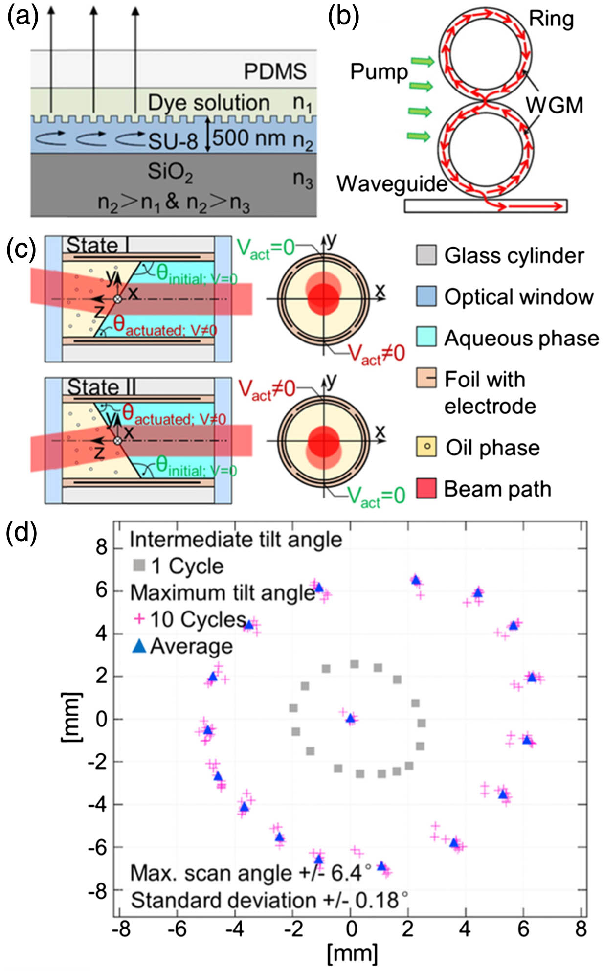
Fig. 2. (a) Schematic of a three-layer optofluidic switch with four optical facets. The arrows show the directions of both incident and reflected/transmitted laser beams. (b), (c) Working mechanism of an acoustic-driven optofluidic switch (b) without and (c) with acoustic excitation. (d) Schematic of a liquid-filled out-of-plane lens. The inset illustrates the cross section of the device. (e) Schematic of an in-plane optofluidic lens. The high-RI fluid medium forms a biconvex microlens that focuses the incident light. (f), (g) Experimental images on (f) the biconvex microlens and (g) the biconcave microlens. (a) Reproduced with permission [31], Copyright 2004, American Institute of Physics. (b), (c) Reproduced with permission [32], Copyright 2012, American Institute of Physics. (d) Reproduced with permission [35], Copyright 2010, Optical Society of America. (e)–(g) Reproduced with permission [41], Copyright 2017, Optical Society of America.
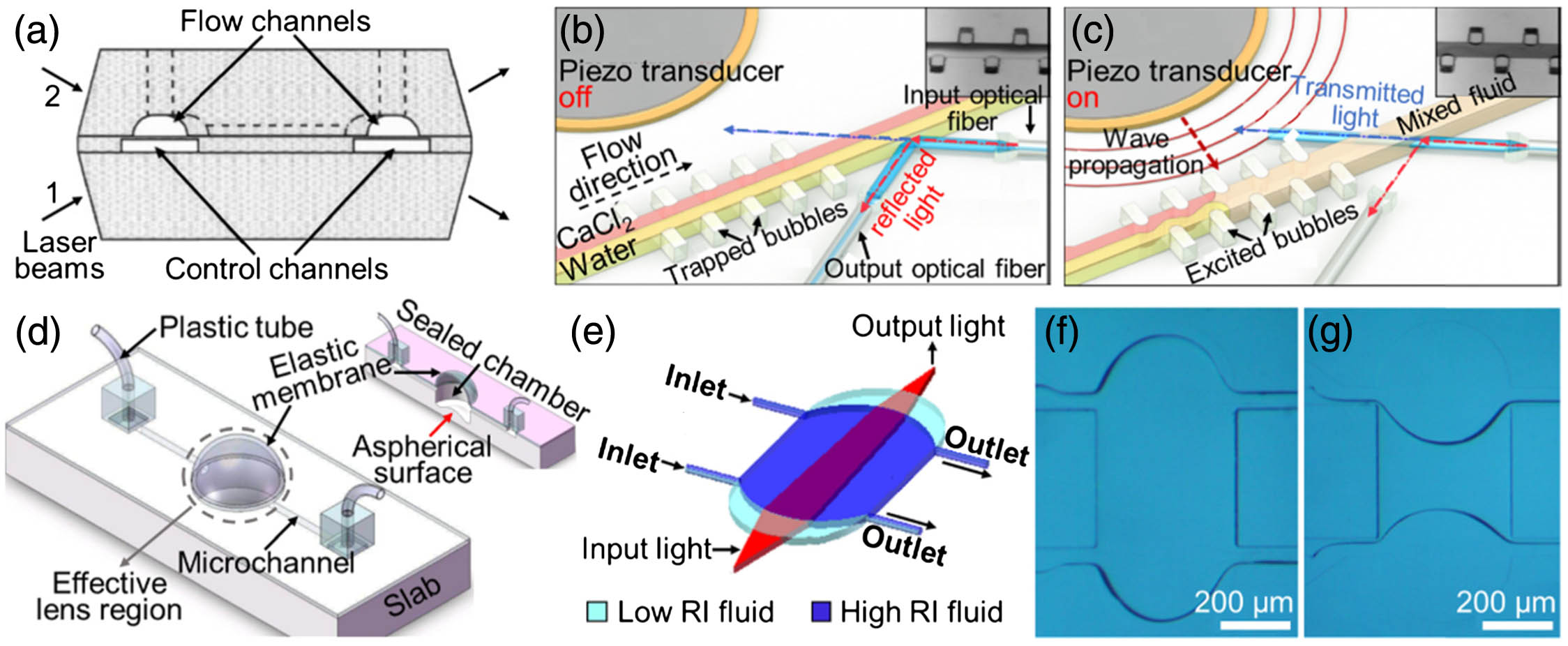
Fig. 3. (a) Planar waveguide integrated on-chip to create a light sheet directly on the sample. (b) Optofluidic lens integrated on-chip to focus a light sheet at the center of a fluidic channel, where multiple samples are automatically scanned and reconstructed in 3D. (c) Working principle of single-beam interferometry. (a) Reproduced with permission [64], Copyright 2014, Royal Society of Chemistry. (b) Reproduced with permission [65], Copyright 2016, Royal Society of Chemistry. (c) Reproduced with permission [69], Copyright 2017, Nature Publishing Group.
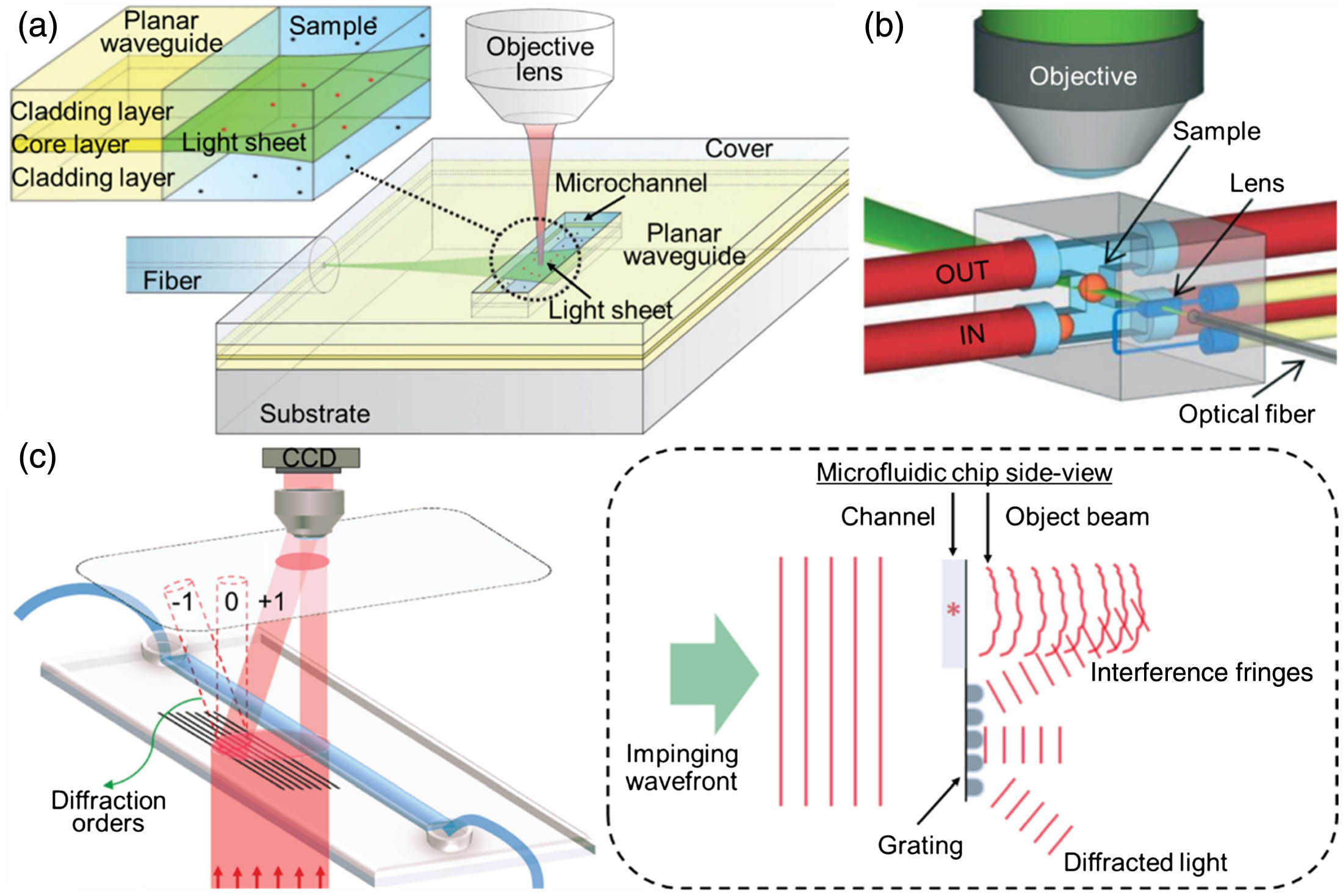
Fig. 4. Examples of an OFM. (a) Schematic of an OFM device (top view). The OFM apertures (white circles) are defined on a 2D CMOS image sensor (light gray dashed grid) coated with Al (gray) and span across the whole microfluidic channel (blue lines). (b) Upright operation mode of the OFM device. (c) Low-resolution sequence of a single RBC to a high-resolution image. (d) Schematics of an FZP-based fluorescence optofluidic microscope. A sample flows in the microfluidic channel on top of the image sensor. The FZP array creates an array of foci inside the channel. (e) Layout for MISHELF microscopy with detuned illumination/detection using IRRB/RGB multiplexing. (a), (b) Reproduced with permission [16], Copyright 2008, National Academy of Sciences of the USA. (c) Reproduced with permission [71], Copyright 2011, PLOS. (d) Reproduced with permission [76], Copyright 2011, Royal Society of Chemistry. (e) Reproduced with permission [77], Copyright 2017, Nature Publishing Group.
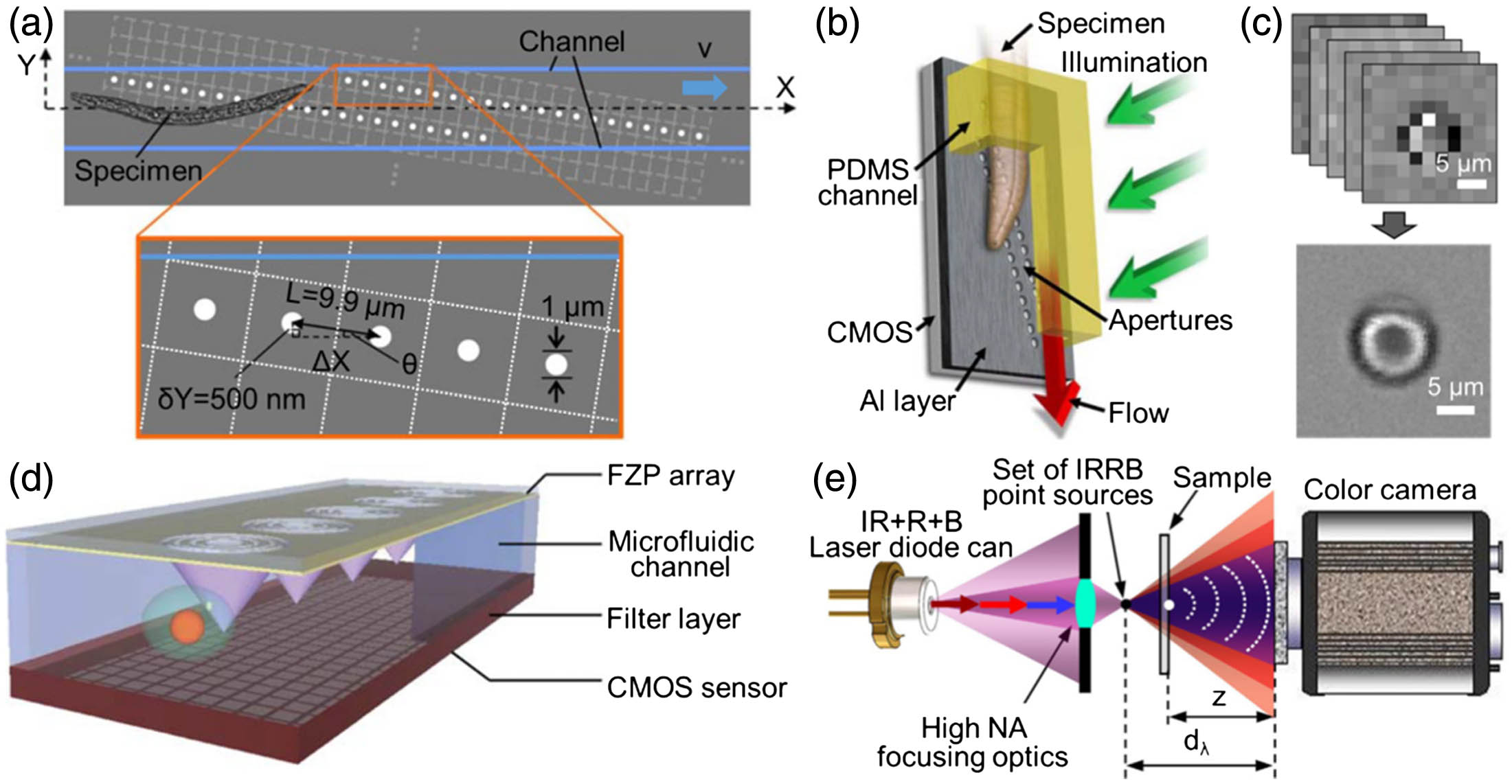
Fig. 5. Different lens-free tomographic microscopes. (a) Schematic of a tomographic microscope device integrated with a shifting aperture. (b) An array of static light sources, e.g., fiber-coupled LEDs are used to create lens-free holograms. (c) “Rainbow” artifact in the reconstructed holograms. (d) Result of the YUV colorization method. (e) An image of the same sample with a 20 × NA = 0.5
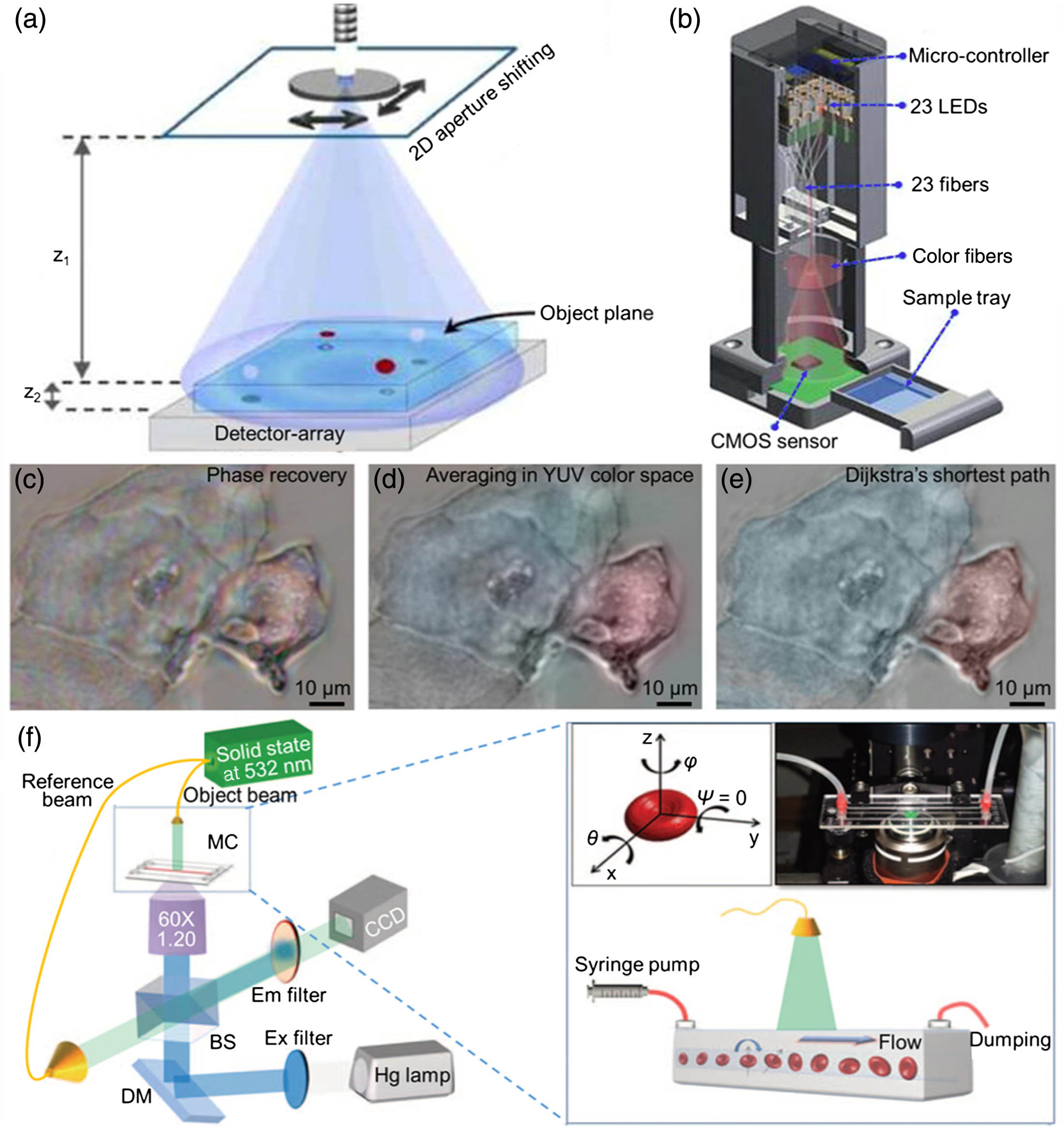
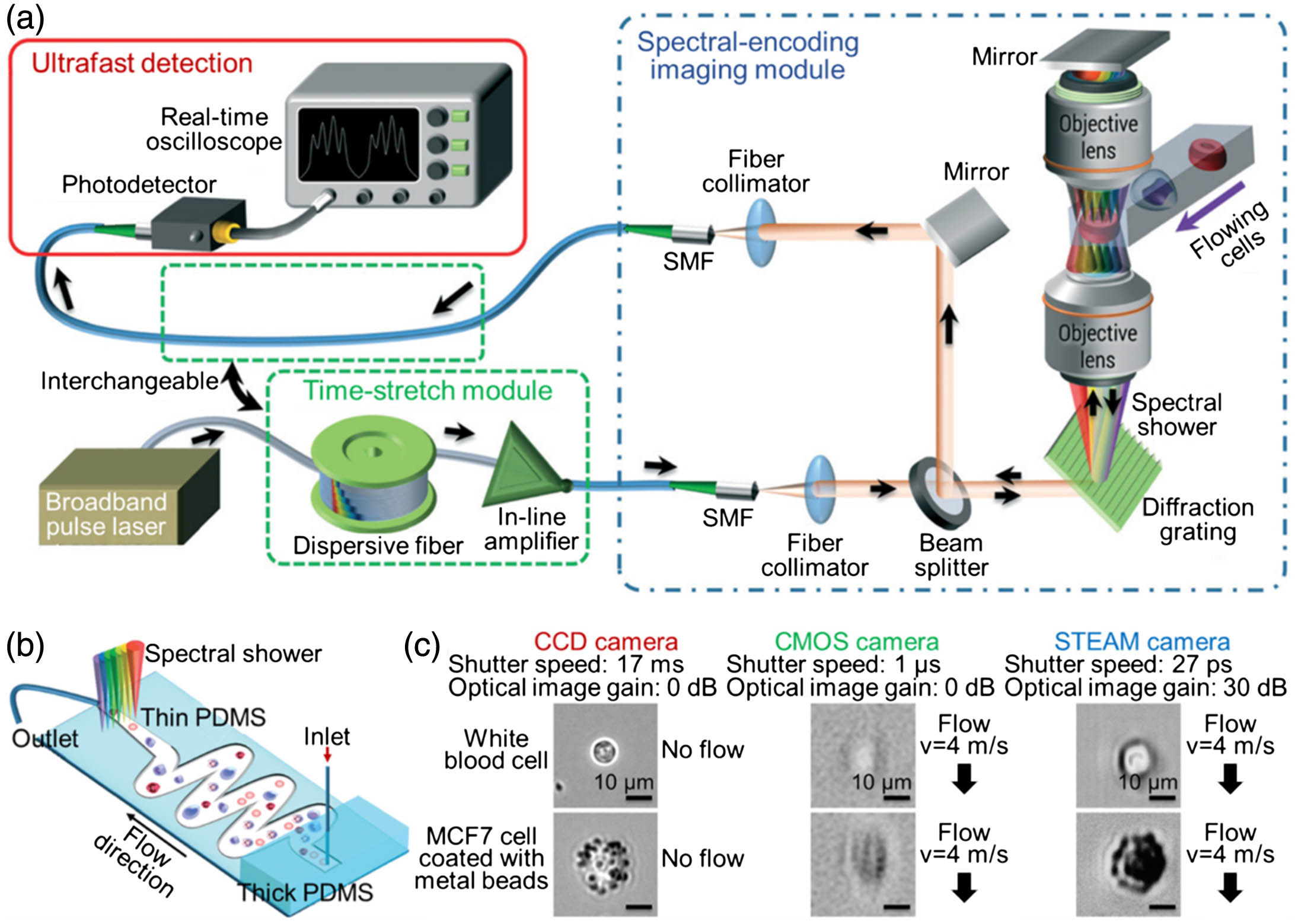
Fig. 6. (a) Schematics of optofluidic time-stretch imaging. (b) Microfluidic channel design used for time-stretch imaging, which relies on an inertial focusing scheme to constrain the position of flowing cells into a straight stream in the imaging region. (c) White blood cell and stained MCF7 cell images captured with CCD, CMOS, and time-stretch cameras. The scale bars represent 10 μm. (a), (b) Reproduced with permission [91], Copyright 2016, Royal Society of Chemistry. (c) Reproduced with permission [95], Copyright 2012, National Academy of Sciences of the USA.
Sihui Chen, Rui Hao, Yi Zhang, Hui Yang. Optofluidics in bio-imaging applications[J]. Photonics Research, 2019, 7(5): 05000532.


 PDF全文
PDF全文

