Photonics Research, 2020, 8 (8): 08001278, Published Online: Jul. 14, 2020
Geometric-phase-induced arbitrary polarization and orbital angular momentum generation in helically twisted birefringent photonic crystal fiber  Download: 685次
Figures & Tables
Fig. 1. Schematic of (left) three-dimensional structure and (right) cross section of TB-PCF. The number of rings in the three-dimensional sketch is reduced for clarity. The simulation is carried out for the cross section shown in the right panel. The dashed lines are a square with the side length of 2 Λ
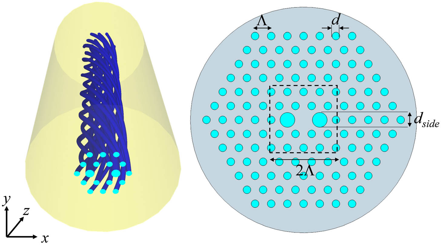
Fig. 2. (Top left) n eff B L pol α pol d side n eff

Fig. 3. Optical power in the core of TB-PCFs as a function of propagation distance for different values of d side α = 0.006 rad / μm

Fig. 4. (Left) Stokes parameters of TB-PCF for d side = 2.0 μm α = 0.006 rad / μm S 3 d side

Fig. 5. (Left) Stokes parameters of TB-PCF for d side = 2.0 μm α = 0.006 rad / μm S 3 d side


Fig. 7. S 3 α = 0.006 rad / μm d side E y

Fig. 8. (Left) Optical power in the core of TB-PCFs and (right) S 3 α d side = 2.5 μm

Fig. 9. (Left) Transmission spectra of TB-PCFs for α = 0.006 rad / μm d side E x S 3

Fig. 10. Stokes parameters of periodically inverted TB-PCF calculated by (left) the analytical method and (right) BPM. d side = 2.0 μm α = 0.0024 rad / μm Λ twist / 4

Fig. 11. Poincaré sphere plots of the polarization state in TB-PCF with d side = 2.0 μm α = 0.0024 rad / μm α = 0.0024 rad / μm α = 0.006 rad / μm

Fig. 12. Stokes parameters of periodically inverted TB-PCF calculated by BPM. d side = 1.25 μm α = 0.000314 rad / μm Λ twist / 4


Fig. 14. Overlap powers (blue solid lines) and total Poynting vectors (black dashed lines) as functions of propagation distance for (left) LP 11 b x LP 21 b x

Fig. 15. Overlap powers (green and blue) and total Poynting vectors (black) as functions of periodically inverted multimode TB-PCF for (top) LP 11 b x LP 21 b x


Takeshi Fujisawa, Kunimasa Saitoh. Geometric-phase-induced arbitrary polarization and orbital angular momentum generation in helically twisted birefringent photonic crystal fiber[J]. Photonics Research, 2020, 8(8): 08001278.


 PDF全文
PDF全文

