Chinese Optics Letters, 2016, 14 (1): 010006, Published Online: Aug. 6, 2018   

Anisotropic edge enhancement in optical scanning holography with spiral phase filtering Download: 1047次

Author Affiliations
1 Bradley Department of Electrical and Computer Engineering, Virginia Tech, Blacksburg, VA 24061, USA
2 Lab of Information Optics and Optoelectronic Technology, Shanghai Institute of Optics and Fine Mechanics, Chinese Academy of Sciences, Shanghai 201800, China
Abstract
Anisotropic edge enhancement is simulated using a spiral phase plate (SPP) in optical scanning holography (OSH). We propose to use a delta function and an SPP as the pupil functions to realize anisotropic edge enhancement. The interference of these two pupils is used to two-dimensionally scan an object to record its edge-only information. This is done in three ways: first, by shifting the SPP, second, by using two offset SPPs of same charge, and finally, by using two oppositely charged SPPs. Our computer simulations show the capability of selectively enhancing the edges of a given object.

A common device to generate helical wavefronts or vortex beams is the spiral phase plate (SPP), which has an azimuthal structure exp[jnφ], where n is the topological charge, which is generally a nonzero integer, and 0φ<2π is the azimuthal coordinate[1,2]. The simplest SPP realized with n=1 has been demonstrated as a spatial filter in a 4f system to achieve edge enhancement[3], and more recently, it was used as a pupil function for isotropic edge extraction in optical scanning holography (OSH)[4].

Edge enhancement has found utility in a variety of image processing applications where detecting the edge or shape is of interest, such as in industrial inspections[5,6], and fingerprint identification[7,8]. Generally, the enhancement effect is isotropic or symmetrical such that regardless of orientation, each edge of the input pattern is enhanced uniformly. However, in some cases, the feature information around certain orientations and edges is of greater interest and therefore requires anisotropic edge enhancement to emphasize these edges. The methods reported for selective edge enhancement include changing the integer power and offset angle of the sine function in the vortex distribution[9], fractional[10] or shifted vortex filters[11,12], a superposed vortex amplitude filter[13], and the introduction of astigmatism in the vortex filter[14].

The use of SPPs for enhancement effects in digital incoherent holography was first attempted using the Fresnel incoherent correlation holography technique[15], and then by OSH[4]. The former approach is based on self-interference and requires the capture of three phase-shifted recordings sequentially, which could introduce bias build-up when using complex objects[16]. The latter overcomes this by heterodyne scanning the object such that the holographic information is carried by the heterodyne frequency, which can be extracted using electronic filtering. With the scanning property, OSH can be applied in a variety of fields, ranging from microscopes to remote sensing[17,18].

In this Letter, we demonstrate the use of OSH to record selective edge-only information of an object holographically. We introduce three methods to do this: (1) shifting the position of the SPP to position (r0,φo) in the pupil plane, (2) using two symmetrically offset vortices of the same charge, and (3) using two oppositely charged offset vortices.

OSH is based on a two-pupil optical heterodyne image processor[19,20] that captures the entire holographic information of an object with a two-dimensional (2D) scan while preserving the phase information in the recording process. The two pupils in the standard OSH system are such that one pupil is a uniform function or a plane wave and the other is a delta function or point source. The interference of these two pupils is used to 2D scan an object to extract its holographic information.

The two pupil functions, p1(x,y) and p2(x,y), in the two-pupil heterodyne scanning image processor presented in Fig. 1 are located in the front focal plane of lens L1 with focal length f. The pupils are illuminated by collimated laser beams with temporal frequencies ω0 and ω0+Ω, respectively, where ω0Ω and the frequency shift Ω results from an acousto-optic modulator. The laser beams are then combined by beam splitter (BS) and used to scan over an object of amplitude distribution Γ0(x,y;z) located a distance z away from the focal plane of Lens L1. Note that the scanning is done by placing the object on an xy scanning platform, as shown in Fig. 1. The lens L2 is a Fourier transform lens with mask M(x,y) located at its back focal plane. The photodetector (PD) collects all the transmitted light and gives an output current, which consists of a baseband and heterodyne current.

Fig. 1. Two-pupil heterodyne scanning image processor.

下载图片 查看所有图片

An electronic bandpass filter tuned to the heterodyne frequency Ω gives a heterodyne current iΩ. This heterodyne current will serve as an input to a lock-in detection system shown in Fig. 2 to give the in-phase current ic(x,y;z) and quadrature current is(x,y;z) as outputs[19]. When the system operates in an incoherent mode, i.e., when M(x,y)=1:ic(x,y)=Re[J1{J{|Γ0(x,y;z)|2}×OTFΩ}dz],is(x,y)=Im[J1{J{|Γ0(x,y;z)|2}×OTFΩ}dz].

Fig. 2. Electronic demodulation system ( is electronic multiplier).

下载图片 查看所有图片

Note that in the above equations, we have performed the integration over the depth, i.e., over z, of the three-dimensional object, |Γ0(x,y;z)|2, where we have assumed the object is a collection of 2D planar distributions. The symbols J and J1 in Eqs. (1) and (2) denote the Fourier transform and its inverse, respectively, which are defined as J{g(x,y)}=g(x,y)e(jkxx+jkyy)dxdy and J1{G(kx,ky)}=1/(4π2)G(kx,ky)e(jkxxjkyy)dkxdky with kx and ky denoting the spatial frequencies of x and y, and with the function G denoting the transform of the function g. The OTFΩ is the optical transfer function of the overall system, which is given by[19]: OTFΩ=p1*(x,y)p2(x+fk0kx,y+fk0ky)×exp(jzf(xkx+yky))dxdy,where k0 is the wavenumber, f is the focal length of Lens L1, and z is the distance from the focal plane of Lens L1, as shown in Fig. 1.

Equations (1) and (2) give two processed images of the intensity function |Γ0(x,y;z)|2 of the two-pupil heterodyning image processing system.

A complex hologram recorded by the system is achieved by adding Eqs. (1) and (2) as follows. Hc(x,y)=ic(x,y)+jis(x,y)=J1{J{|Γ0(x,y;z)|2}×OTFΩ}dz.

An SPP was first demonstrated in the OSH imaging system in Ref. [4] where the SPP was used as one of the pupil functions. Thus, for the OSH system, the pupil functions are p2(x,y)=δ(x,y),p1(x,y)=ψn(r,φ),where ψn(r,φ)=exp(jnφ)exp((r/ω)2) is the transmission function of an SPP in polar coordinates r=x2+y2 and φ=tan1(y/x) and ω is the Gaussian beam waist of the optical beam illuminating the SPP. The resulting complex recording of the system, using Eqs. (3) and (4), becomes Hc(x,y)=J1{J{|Γ0(x,y;z)|2}p1*(fk0kx,fk0ky)×exp(jz2k0(x2+y2))}.

In Eq. (7), the object is assumed to be a 2D planar object for simplicity. Equation (7) is a complex hologram where the spectrum of the object has been processed by p1*. The processed image is reconstructed from the hologram by simply convolving it with the spatial impulse response h(x,y;z)=exp(jk0z)jk02πzexp(jk02z(x2+y2)).In this Letter, we will explore anisotropic edge detection with p1(x,y) as an offset SPP, or two symmetrically offset SPPs. The functional forms for the cases are:

Method 1: Anisotropic Filtering by Shifting the SPP

One approach to break the symmetry of the SPP is to shift the singularity away from the origin to a user-specified position in polar coordinates (r0,φ0), where r0>0 and φ0[0,2π]. This is accomplished by shifting the SPP and illuminating it with a Gaussian beam such that the transmission function of this SPP is given by[11]: p1(x,y)=ψ1(r,φ,r0,φ0)=exp(jφs)exp((rs/ω)2),where x0=r0cos(φ0), y0=r0sin(φ0), φs=tan1(yy0/xx0), and rs=(xx0)2+(yy0)2. This idea of breaking the symmetry of the SPP for anisotropic edge detection has previously been realized in a 4f; coherent system[11].

Method 2: Anisotropic Filtering by Shifting Two Symmetrically Offset SPPs With the Same Charge

In this case, the pupil becomes p1(x,y)=ψ1(r,φ,r0,φ0)+ψ1(r,φ,r0,π+φ0).

Method 3: Anisotropic Filtering by Shifting Two Symmetrically Offset SPPs With Opposite Charges

In this case, the pupil is p1(x,y)=ψ1(r,φ,r0,φ0)+ψ1(r,φ,r0,π+φ0).

The holographic recordings and subsequent reconstructions are simulated in MATLAB with the implementation parameters f=300mm, λ=633nm, and ω=2mm, with an SPP topological charge of n=±1, and an input object with the dimensions of 20mm×20mm. The initial phase of the SPP is set to be 0, if it is not specified. From the simulation results, we will show that in method 3, the initial phase plays a very important role in the modulation.

a. Results of Method 1:

The original object used in the simulation is shown in Fig. 3(a), with the corresponding magnitude spectrum of the object shown in Fig. 3(b). Since the DC value of the spectrum is comparatively large, the logarithmic magnitude spectrum is displayed. When a single-offset SPP is used for edge extraction, the result is dependent on the shift of the center of the SPP from the origin. When the shift r0 is 5 mm and the angle φ0 is 0, the output contains edges enhanced in the horizontal direction, as shown in Fig. 4. The magnitude of the optical transfer function, |OTF|, as calculated from Eq. (3), and the corresponding reconstructed image intensity, simulated using the hologram in Eq. (7), are shown in Figs. 4(a) and 4(b), respectively. As the angle of the shift direction is changed, edges from different orientations can be extracted selectively. Orientation-based edge enhancements are presented in Figs. 4(c) and 4(d), for which r0 is unchanged and φ0 is 3π/4 and π/2, respectively. It should be noted that there are some imperfect defects in the output images because of aliasing during simulation.

Fig. 3. (a) Original object and (b) its logarithmic magnitude spectrum.

下载图片 查看所有图片

Fig. 4. (a) |OTF| [fx and fy are spatial frequencies in unit of 1/mm] and (b) reconstructed image of single-offset SPP with 5 mm shift in the horizontal direction. (c) and (d) Output images of the single-offset SPP with different shift directions.

下载图片 查看所有图片

b. Results of Method 2:

When two SPPs with the same charge are used as the pupil, the OTF seems to exhibit properties of high-pass filtering regardless of the shift distance. The simulated |OTF| results for shifting two SPPs 2.5 and 5 mm are shown in Figs. 5(a) and 5(c), respectively. The reconstruction results in Figs. 5(b) and 5(d) illustrate that filtering is more directional or anisotropic as the separation between the two SPPs increases. By comparing the results in Figs. 4 and 5, it is reasonable to draw a conclusion that two-SPP pupil filtering is better than one-SPP filtering when the SPP shifts are the same.

Fig. 5. (a) and (b) |OTF| and the reconstructed image of the two-offset SPP pupil with same charge and 5 mm shift. (c) and (d) |OTF| and the reconstructed image of the two-offset SPP pupil with same charge and 2.5 mm shift.

下载图片 查看所有图片

Another difference between the single-offset SPP and two-offset SPPs can be illustrated using a white square object on a dark background. The results from using a two-offset SPPs pupil have double lines at the extracted edge, while those from using a single-offset SPP produces one line at the edge, as seen in Figs. 6(b) and 6(a), respectively. This effect is because the single-offset SPP pupil corresponds to single-sided filtering, which approximates a first-order derivative, while a two-offset SPPs pupil is double-sided filtered, which gives a second-order derivative[21]. In fact, double-sided filtering gives zero cross detection on the edge and is the reason a double line is observed at the edge location in Fig 6(b).
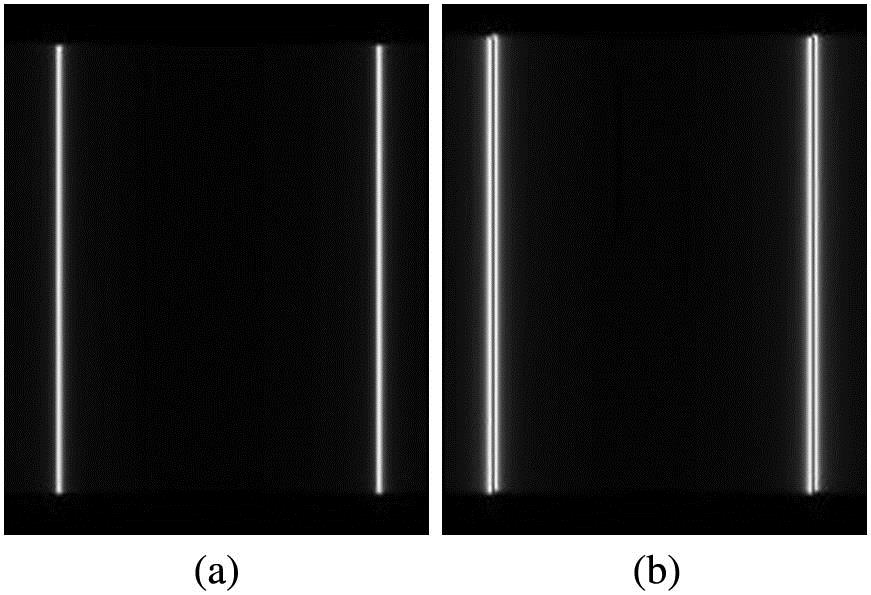
Fig. 6. Comparison of the edge extracted images of a square object using (a) single-offset SPP and (b) two-offset SPPs.

下载图片 查看所有图片

c. Results of Method 3:

For two offset SPPs of opposite charges, the |OTF| and its corresponding reconstructed image for a shift distance r0=2.5mm; in the horizontal direction, φ0=0, are shown in Figs. 7(a) and 7(b), respectively. The selective edge enhancement of this pupil is an improvement over double-offset SPPs of same charge in the vertical direction such as at the top and bottom of the object, where the edges are suppressed more distinctly. From the |OTF|s shown in Figs. 7(a) and 5(c), the difference between these two pupils can be seen especially when examining the area around fx=0, where the two pupils meet.
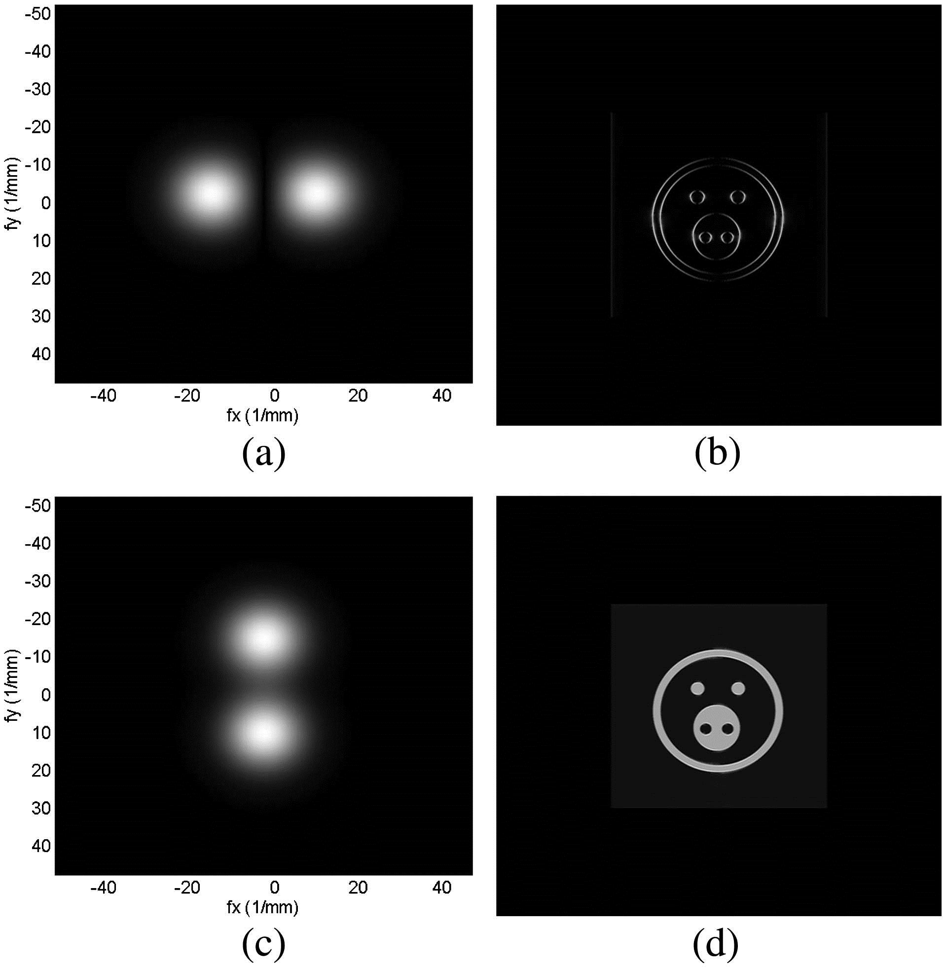
Fig. 7. (a) |OTF| and (b) reconstructed image of the two-offset SPPs as a pupil with opposite charges and 2.5 mm shift, (c) |OTF| and (d) reconstructed image of the two-offset SPPs as a pupil with opposite charges in the vertical direction.

下载图片 查看所有图片

If the two SPPs are shifted in the vertical direction, φ0=π/2, the DC information will not be filtered and leads to a non-edge-enhanced image, as shown in Figs. 7(c) and 7(d). Therefore, the shift direction should be considered in the two-offset SPPs pupil function design with opposite charges. After a simple calculation, the pupil function in the form p1(x,y)=ψ1(r,φφ0,r0,φ0)+ψ1(r,φφ0,r0,π+φ0).will have capability of anisotropic edge extraction regardless of the shift direction. The simulation results under this pupil function are shown in Fig. 8 for two different shift directions and demonstrate the feasibility of the pupil function design.
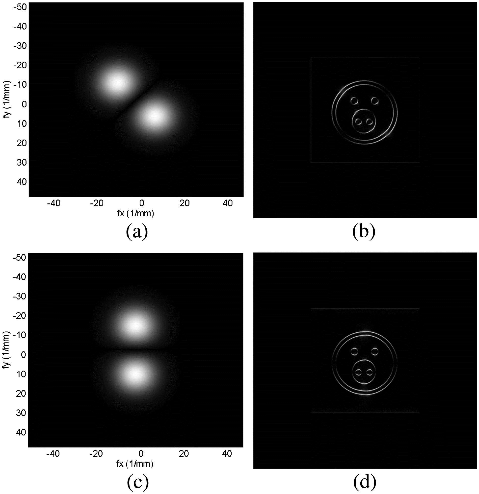
Fig. 8. Improved |OTF| and the reconstructed images of the two-offset SPPs as a pupil with opposite charges in the form of Eq. (11), and φ0 is (a) and (b) 3π/4 and (c) and (d) π/2.

下载图片 查看所有图片

In conclusion, we propose three methods to realize anisotropic filtering in an OSH system using SPPs as one of the pupil functions. The first method shifts the vortex filter in the pupil plane, the second method employs two symmetrically offset vortices of the same charge, and the third method uses two symmetrically offset vortices of opposite charges. Anisotropic edge enhancement effects are demonstrated for all three methods in the computerimulations. The single-shifted SPP produces selective edge enhancement results for large shift distances but cannot remove the low-frequency information when shift distances are small. Anisotropic edge enhancement results for small shift distances are obtained by adding a same charge or opposite charge SPP in the radially opposite direction, as illustrated in the second and third methods, respectively. Further, method 3 demonstrated anisotropic edge enhancement more distinctively than method 2, as more information in the direction perpendicular to the SPP orientation is filtered out. Additional areas of investigation include comparing results from the computer simulations to those from experimental investigations and implementing other anisotropic filtering approaches.

References

[1] KotlyarV. V.KhoninaS. N.KovalevA. A.SoiferV. A.ElfstromH.TurunenJ., Opt. Lett.31, 1597 (2006).OPLEDP0146-9592

[2] KotlyarV. V.KovalevA. A.SkidanovR. V.MoiseevO. Y.SoiferV. A., J. Opt. Soc. Am. A24, 1955 (2007).JOAOD60740-3232

[3] GuoC.-S.ZhangY.HanY.-J.DingJ.-P.WangH.-T., Opt. Commun.259, 449 (2006).OPCOB80030-4018

[4] PanY.JiaW.YuJ.DobsonK.ZhouC.WangY.PoonT.-C., Opt. Lett.39, 4176 (2014).OPLEDP0146-9592

[5] GonzalezR. C.WoodsR. E., Digital Image Processing, 2nd ed. (Prentice Hall, 2002).

[6] MárquezA.NeippC.BeléndezA.GallegoS.OrtuñoM.PascualI., Opt. Lett.28, 1510 (2003).OPLEDP0146-9592

[7] GreenbergS.KoganD., Opt. Eng.44, 127004 (2005).

[8] ChenX.TianJ.ZhangY.YangX., Lect. Notes Comput. Sci.3832, 302 (2005).LNCSD90302-9743

[9] SharmaM. K.JosephJ.SenthilkumaranP., Appl. Opt.50, 5279 (2011).APOPAI0003-6935

[10] DavisJ. A.NowakM. D., Appl. Opt.41, 4835 (2002).APOPAI0003-6935

[11] SituG.PedriniG.OstenW., J. Opt. Soc. Am. A26, 1788 (2009).JOAOD60740-3232

[12] SharmaM. K.JosephJ.SenthilkumaranP., J. Opt.42, 1 (2013).

[13] SharmaM. K.JosephJ.SenthilkumaranP., Opt. Laser Technol.57, 230 (2014).OLTCAS0030-3992

[14] SharmaM. K.JosephJ.SenthilkumaranP., Opt. Laser Technol.50, 1501 (2012).OLTCAS0030-3992

[15] BouchalP.BouchalZ., Opt. Lett.37, 2949 (2012).OPLEDP0146-9592

[16] PoonT.-C., Nat. Photon.2, 131 (2008).NPAHBY1749-4885

[17] IndebetouwG.ZhongW., J. Opt. Soc. Am. A23, 1699 (2006).JOAOD60740-3232

[18] SchillingB. W.TempletonG. C., Appl. Opt.40, 5474 (2001).APOPAI0003-6935

[19] PoonT.-C., Optical Scanning Holography with MATLAB (Springer, 2007).

[20] PoonT.-C.KorpelA., Opt. Lett.4, 317 (1979).OPLEDP0146-9592

[21] YangX.JiaW.WuD.PoonT.-C., Amer. J. Phys. (submitted).

Kelly K. Dobson, Wei Jia, Ting-Chung Poon. Anisotropic edge enhancement in optical scanning holography with spiral phase filtering[J]. Chinese Optics Letters, 2016, 14(1): 010006.

本文已被 3 篇论文引用
被引统计数据来源于中国光学期刊网
引用该论文: TXT   |   EndNote

相关论文

加载中...

关于本站 Cookie 的使用提示

中国光学期刊网使用基于 cookie 的技术来更好地为您提供各项服务,点击此处了解我们的隐私策略。 如您需继续使用本网站,请您授权我们使用本地 cookie 来保存部分信息。
全站搜索
您最值得信赖的光电行业旗舰网络服务平台!