光学学报, 2018, 38 (12): 1206001, 网络出版: 2019-05-10
利用激光打标法制备侧面均匀发光聚合物光纤  下载: 1152次
Uniform Side-Glowing Polymer Optical Fiber Fabricated by Laser-Marking
图 & 表
图 1. 利用激光打标法在POF上制备VLS光栅示意图
Fig. 1. Schematic of fabrication of VLS grating on POF by laser-marking
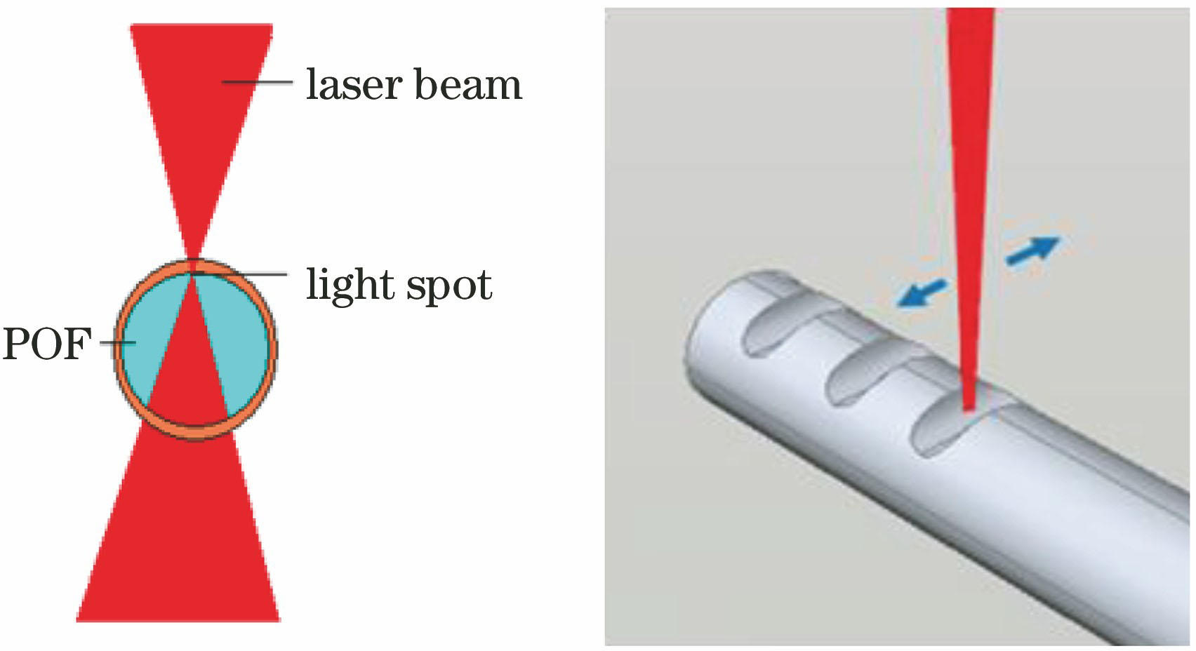

图 3. 不同散射颗粒半径下散射光强随散射角的变化曲线
Fig. 3. Scattering light intensity versus scattering angle under different scattering particle radii


图 5. 散射点散射光功率随(a)散射点凹坑深度h和(b)散射颗粒密度N的变化曲线
Fig. 5. Scattering light power of scattering point versus (a) scattering point pit depth h and (b) scattering particle density N

图 6. 不同(a)散射点凹坑深度和(b)相对出射度时的VLS栅距分布曲线
Fig. 6. VLS grating pitch distributions under different (a) scattering point pit depths and (b) relative emissivities

图 7. POF侧面散射点的显微照片。(a)不通光; (b)通光
Fig. 7. Microscopic images of scattering points on POF side. (a) No light; (b) with light

图 8. 不同激光功率打标后的POF光栅发光显微照片。(a) 2 W; (b) 4 W; (c) 6 W; (d) 8 W; (e) 10 W; (f) 12 W; (g) 14 W; (h) 16 W; (i) 18 W; (j) 20 W
Fig. 8. Luminescence microscopic images of POF grating after laser marking with different laser powers. (a) 2 W; (b) 4 W; (c) 6 W; (d) 8 W; (e) 10 W; (f) 12 W; (g) 14 W; (h) 16 W; (i) 18 W; (j) 20 W

图 9. POF散射归一化光强随打标激光功率的变化曲线
Fig. 9. Normalized scattering intensity of POF versus laser power for marking

图 10. 打标图形。(a)调整前; (b)调整后
Fig. 10. Mark graphics. (a) Before adjustment; (b) after adjustment


表 1SK-20型POF的参数与材料
Table1. Parameters and materials of SK-20 POF
|
表 2激光打标机初始参数
Table2. Initial parameters of laser-marking machine
|
漆宇, 刘楚嘉, 何涌, 郜飞飞, 李梓润, 庄其仁. 利用激光打标法制备侧面均匀发光聚合物光纤[J]. 光学学报, 2018, 38(12): 1206001. Yu Qi, Chujia Liu, Yong He, Feifei Gao, Zirun Li, Qiren Zhuang. Uniform Side-Glowing Polymer Optical Fiber Fabricated by Laser-Marking[J]. Acta Optica Sinica, 2018, 38(12): 1206001.


 PDF全文
PDF全文

