基于现场可编程门阵列和大功率LED阵列光源的小型化水下无线光通信系统的研究与实现
Underwater wireless optical communication (UWOC) featuring high speed, low delay, and high confidentiality can form a medium and short distance local area network (LAN) with high speed and strong real-time properties or can complement the advantages of underwater acoustic communication hybrid networking. It has become a research hotspot in recent years. The deployment and application of UWOC require high-performance, low-cost, and miniaturized practical optical transceivers. By employing a laser diode as a light source, the transmission distance is long with high speed, but the alignment of the light receiver and light sender is demanding, which is difficult for communication of non-fixed positions and orientations in the dynamic seawater environment. If the light-emitting diode (LED) is the light source, the alignment requirements can be greatly reduced, while the LED array can be adopted to enhance the light signals to extend the transmission distance. Meanwhile, the high-order modulation can be utilized to improve the problem of insufficient bandwidths. The existing UWOC systems based on LED design have a large room for improvement in transmission distance and transmission rate. Additionally, the system design can realize real-time high-order modulation, coding and signal processing, and miniaturized system integration by leveraging field programmable gate array (FPGA) at both receiving and transmitting ends, and further improve the system performance and practicality. Aiming at the application requirements of underwater UWOC with high speed, long distance, low cost, and miniaturization, we design a highly robust integrated miniaturized UWOC system based on high-power LED array and FPGA. The system can realize on-off keying (OOK) modulation, and flexibly realize high-order modulation and channel coding. Meanwhile, it can achieve a longer transmission distance and a higher transmission rate than the LED UWOC systems reported in previous references, with miniaturized integration of optical receivers and transmitters.
The optical transmitter employs 45×1 W high-power LED array as the light source and takes total internal reflection (TIR) lens and parabolic reflector tube structure as the optical antenna to realize high-order modulation and coding by FPGA. In terms of optical receivers, an avalanche photodiode-automatic gain amplifier circuit (APD-AGC) optical receiver based on FPGA is designed. After being converted into the current signal by APD, the optical signal is converted into a voltage signal by transresistance amplifier module, then amplified into a voltage signal with fixed peak amplitude by automatic gain amplifier module, and finally input to the analog-to-digital conversion (ADC) module. The receiving FPGA can synchronously demodulate and decode the received signal in real time. In real-time synchronous signal transmission, the receiving and sending ends of the system adopt FPGA to process signals, which can support the real-time synchronous underwater transmission of commonly applied OOK signals and high-order modulation signals by taking 16QAM encoded by Reed Solomon (RS) channel as an example, which can meet the application requirements under different underwater scenarios. Finally, the optical communication receiver and transmitter are miniaturized and integrated with strict waterproof packaging and practical significance.
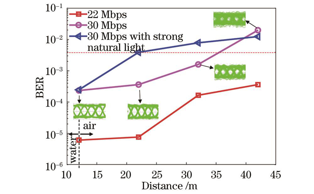
Under a 12 m underwater channel, the UWOC system employs OOK and 16QAM modulation for data transmission. Within the error threshold, the transmission rate of the optical terminal can reach 30 Mbps. The 16QAM bit error rate is always higher than that of the OOK system. This is because QAM modulation requires high real-time synchronization of the signal, and the wide beam of the LED array makes underwater channel synchronization difficult due to the multi-path effect. However, at the same transmission rate, 16QAM has a higher bandwidth utilization than OOK modulation, which is because the system is limited by ADC sampling rate and synchronization algorithm, the bandwidth advantage of 16QAM high-order modulation signal is not fully utilized, and there is still great potential in rate improvement. In terms of robustness, the receiver can achieve effective reception of the deviation degree from the main optical axis within 40° at a distance of 12 m, reducing the difficulty of alignment and possessing strong robustness. To test the limit transmission distance of the system, we successfully build a cross-media link communication system with a distance of 12 m water+30 m air (a total of 42 m) and transmit 22 Mbps nonreturn to zero (NRZ)-OOK shaper signal within the error decision threshold. In practical applications, the system can be applied to underwater scenarios. For example, it can be carried on the submarine to achieve underwater link deployment, and underwater node information collection or signal transmission. Additionally, its high-power LED array also supports the deployment of air-water link wireless optical communication links, such as the deployment of end machines on ships and underwater frogman or underwater robot community information interaction.
We design and develop a high-robustness miniaturized UWOC system based on FPGA and high-power LED array light source, which supports traditional OOK modulation and m-QAM modulation. The system is tested experimentally by taking 16QAM modulation as an example, and the results show that under the real-time transmission of a 12 m water channel, the bit error rates for OOK modulation and 16QAM modulation are 2.467×10⁻⁴ and 3.467×10⁻³ respectively at 30 Mbps. The 22 Mbps NRZ-OOK shaping signal 12 m water +30 m air is transmitted across media links with a bit error rate of 3.619×10⁻⁴. Additionally, the light source transmitter of a high-power LED array with optical collimation antenna and the optical receiver based on 3 mm large aperture APD automatic gain control can receive signals within 40° of the main optical axis in the 12 m underwater channel. Finally, the stringent requirements for UWOC system alignment and focusing are greatly reduced, and the system robustness for applications in the underwater environment is improved.
1 引言
海洋生态的监测与保护、灾害与污染预警、资源勘探与开发等,都离不开水下信息的采集与无线通信[1-5]。水下无线光通信(UWOC)以其高速率、低延迟、高保密性等特点,可组成速率高、实时性强的中短距离的局域网,或可与水声通信优势互补混合组网,近年来成为了研究热点。
UWOC的部署与应用,需要高性能、低成本、小型化的实用化光端机。采用激光二极管(LD)作光源,传输距离远、速率高,但对光收、发端机的对准要求苛刻,这对于动态海水环境下非固定位置和取向的通信是很困难的。若以发光二极管(LED)作光源,则可大幅度降低对准的要求,同时可以采用LED阵列增强光信号以延长传输距离,采用高阶调制以改善其带宽不足的问题。2010年,Doniec等[6]采用6×5 W的蓝色发光二极管和雪崩光电二极管(APD)构建小型水下光端机,实现了1.2 Mbps速率的30 m距离水下通信。2015年,Son等[7]采用6 W的LED和APD,并结合菲涅耳透镜,设计了一种可变焦的光通信端机,在清水中实现了25 m距离、5 Mbps速率的传输。2018年,Wang等[8]利用LED光源构建通信系统,实现了10 m水下信道25 Mbps速率的含Reed Solomon(RS)信道编码的开关键控(OOK)信号的实时传输。2021年,Dong等[9]采用菲涅耳透镜作为光学天线,设计了一种水下无线蓝光LED通信样机,可实现距离为20 m、通信速率为5 Mbps的水下通信。同年,Lin等[10]采用圆偏振光作为通信载体,设计了一种双信道UWOC系统 “Shrimp”。2021年,Liang等[11]设计了一种双光源水下光通信端机,可实现APD接收25 m距离、5 Mbps速率和光电倍增管(PMT)接收50 m距离、5 Mbps速率的水下通信。由上可看出,基于LED设计的UWOC系统,不管是在传输距离还是传输速率上,都还有较大的改进空间,同时,系统的设计可以通过在收发端均利用现场可编程门阵列(FPGA),以实现高阶调制、编码和信号处理及小型化系统的集成,进一步提高系统的性能和实用化。
本文针对水下高速、长距离、低成本和小型化的UWOC应用需求,设计了一种高鲁棒性的基于大功率LED阵列和FPGA的集成小型化UWOC系统,该系统既可实现OOK调制,也可以灵活地实现高阶调制和信道编码,与已有文献报道的LED UWOC系统相比,实现了较长的传输距离和较高的传输速率,以及光收发端机的小型化集成。
2 系统原理
本文设计的基于FPGA的系统集成小型化UWOC系统原理框图,如

图 1. 基于LED或LED阵列和FPGA的UWOC系统构成框图
Fig. 1. Architecture of UWOC system based on LED or LED array and FPGA
2.1 NRZ-OOK脉冲整形
光通信中最简单且常用的调制方式为OOK调制,它利用传输信号的电平来驱动LED光源的开和关,其特点是功耗小、抗干扰能力强。传统的OOK调制电路适合驱动小功率LED光源,而驱动高速调制的大功率LED光源存在困难[11]。在大功率LED光源UWOC系统中,需要在信号调制部分使用高线性、高带宽增益积运算放大器,将FPGA生成的高速OOK小信号无损伤地放大成大信号,再通过bias-tee器件加入直流偏置调制到大功率LED阵列的光载波上。此外,大功率LED光源水下光发射机对LED光源自身的带宽、偏置bias-tee器件的驻波比、前级放大器之间阻抗匹配等性能要求比较严苛,需要在系统电路设计时统筹考虑加以解决。在本文设计的电路系统中已解决此问题
光通信中常利用限幅放大器生成矩形双极性OOK信号,即TTL数字调制,既保证信号质量同时占用等量的带宽。为了减轻LED的带宽限制引起的符号间干扰(ISI),这里设计的信号不直接发送矩形双极性OOK信号,而是发送非归零(NRZ)-OOK脉冲整形信号。在信号处理中,根升余弦滤波器(RRC),常被用作发射端的脉冲整形滤波器和接收端的匹配滤波器,生成具有升余弦频率响应的脉冲信号。Hrrc(f)是升余弦滤波器的频率响应Hrc(f)的平方根,即Hrc(f)=Hrrc(f)∙Hrrc(f),则有|Hrrc(f)|=
在本文设计中,滤波器是通过Altera FIR Ⅱ滤波器IP核实现的。如

图 2. NRZ-OOK脉冲整形信号的Modelsim仿真图
Fig. 2. Modelsim simulation diagram of NRZ-OOK pulse shaping signal
在接收端,NRZ-OOK脉冲整形信号在过零判决后,还需要严格的位同步。本文设计中采用插值算法位同步,可以不改变采样时钟的频率和相位来实现位同步信号的调整,同时,插值算法可以根据采样值以及数控振荡器输出的采样时刻信号和误差信号,获取最佳采样值。
2.2 基于FPGA的高阶调制和信道编码
为了在UWOC系统有限的调制带宽内提高速率,通常选择QAM等高阶调制方式[12-14]。但QAM调制技术需要线性度较好的光源和信道,限制了光源发射光功率的大小,导致采用高阶调制的UWOC系统的水下传输距离较近,在良好水质下传输距离一般不超过20 m。因此,实现高速率、长距离UWOC的关键之一,是采用可高速调制的大功率的光源输出。
下面以16QAM为例来介绍实现m-QAM的实现过程。在光发射端,16QAM调制信号在 FPGA开发板上实现。215-1 bit伪随机数据流先进行串/并转换,生成的4 bit原始信号进行RS信道编码作为外码,随后进行差分编码作为内码,经过星座映射并添加载波信号生成RS-16QAM调制信号。生成的数字信号通过数/模转换(DAC)后由放大器放大,并通过bias-tee偏置器注入直流(DC)电流,一起调制到大功率LED阵列后,转换成大功率的光信号输出。
在光接收端,对16QAM信号进行严格的载波同步和位同步后,还原成I、Q两路信号。本文设计采用判决降级相位检测器(DD)算法载波同步,将接收到的信号根据最近原则判决到最近的量化星座点上[15-16]。载波同步过程中,由直接数字合成器(DDS)生成相干载波,通过鉴相器和环路滤波器实时反馈调整载波的相位与频率。已调16QAM信号与相干载波相乘后,经过滤波器恢复成I、Q两路基带信号。位同步采用基于插值算法的位同步。插值区间由数控振荡器生成,并输入到基于Farrow结构的插值滤波器,以计算两个下变频分支信号,并恢复基带信号的最佳判决时间。插值间隔通过实时反馈进行调整,使用基于Gardner算法的误差检测器和环路滤波器进行计算[15]。随后采用自适应门限判决的方法,周期性训练出星座判决门限,将I、Q两路位同步后的信号进行星座逆映射。最后进行部分差分解码、RS信道译码、串/并变换,还原成m伪随机序列二进制比特码流。基于FPGA实现的系统框图,如
为了解决正交相移键控(QPSK)、16QAM、64QAM等不同调制格式的信号在相干解调时出现的相位模糊问题,差分编码技术作为可行的解决方案之一得到了广泛的关注和研究[17]。差分编码技术可以解决相位模糊现象,但是由于差分编码属于有记忆调制,会引发误码增殖,添加信道编码进行补偿很有必要。
差分编码的模4加法器的表达式[18]为
差分解码模4加法器的表达式为
式中:⊕表示模4加运算;Ak和Bk分别为差分编码前和解码后的数据;Ik和Qk分别为差分编码后和解码前的数据。
在本文设计中,使用了π/2旋转不变QAM映射星座图方法,即部分差分编码进行QAM调制,每个16QAM信号前两比特进行差分编码,后两个16QAM符号比特按照π/2旋转不变QAM映射星座图方法映射,如

图 4. 16QAM部分差分编码调制。(a) 差分编码调制过程;(b) π/2旋转不变映射星座图
Fig. 4. 16QAM partial differential encoding modulation. (a) Differential coding modulation process; (b) π/2 rotation invariant mapping constellation
在本文设计中,16QAM调制信号采用RS信道编码,通过Altera Reed Solomon IP核实现数字视频广播(DVB)标准的RS(220,204)编译码。每个符号中含8比特二进制数,每n=220个数据中有k=204个数据符号和n-k=16个监督符号,能检测一组码中的8个错误。信道编码的应用以增加冗余位为代价实现纠错,可解决UWOC中吸收、散射、噪声等带来的误码,同时补偿部分差分编码引起的误码增殖。
至于误码检测部分,光接收机中设计了误码检测模块对接收到的比特流进行实BER统计,通过USB高速串口使用Signaltap逻辑分析仪,实时查看误码率和信号状态,并在计算机端采集接收后的原始数据,进行误码验证。
2.3 光发射机的设计
光学系统是水下光通信的必备部分,光源的选型、镜片孔径选择、光斑的整形,以及透镜材料等,都会严重影响光通信系统的性能。
光发射机由FPGA开发板、125 Msps采样率DAC、45 W大功率LED阵列、驱动电路、偏置器(bias-tee),以及发射准直天线构成。LED阵列采用5串9并的贴片集成光源芯片,单个芯片额定功率为1 W,实测波长为517 nm,其伏安特性曲线和发光光谱分别如图

图 5. 光发射机性能参数。 (a) 伏安特性曲线 ;(b) 光发射机球积分法实测光谱
Fig. 5. Performance parameters of optical transmitter. (a) Volt-ampere characteristics curve; (b) spectrum measurement using optical transmitter sphere integration method

图 6. 基于FPGA大功率LED阵列的小型光发射机实物图。(a) 光发射机电路实物图片;(b) 光发射机防水封装处理后的工作图
Fig. 6. Physical photo of miniaturized optical transmitter based on FPGA and high-power LED array. (a) Picture of optical transmitter circuit; (b) picture of optical transmitter working after waterproof packaging
设计的系统在大功率LED阵列光发射机上设计发射准直天线,高曲率TIR自由曲面透镜结合抛物面反光杯聚光镜筒结构的设计,有效地减小了LED发散角,,延长了传输距离。该设计结构属于非成像光学系统,发射准直天线可以将LED光束压缩在一个较小的角度范围,从而提高光束的空间能量密度[20-21]。
调制带宽是限制LED光源通信速率的关键指标之一。设计中利用GaN材料制造的LED比传统的InP材料的LED响应速度更快,此外,还要在LED驱动电路中采用更快速的金属氧化物半导体场效应晶体管(MOSFET)或双极结型三极管(BJT)器件,这样可以加快开关速度,提高LED调制的速度。用同一幅度不同频率的正弦波作为输入信号,测试光发射机的幅频响应,结果如
2.4 光接收机的设计
光接收机模块包含FPGA开发板、125 Msps采样率模/数变换(ADC)模块、3 mm光敏面大孔径APD自动增益控制光接收模块、线性电源模块,以及光学接收模块。尺寸为300 mm×200 mm×200 mm,质量为3 kg,接口采用凌科DH20旋转式防水航空连接器。

图 10. 光接收机实物图。(a)光接收机接收OOK信号在示波器显示眼图;(b)光接收机电路实物图
Fig. 10. Physical photo of optical receiver. (a) OOK signal and its eye diagram on oscilloscope received by optical receiver; (b) picture of optical receiver circuit
基于3 mm光敏面大孔径APD设计了一种自动增益控制光接收机,电路如

图 11. 自动增益控制光通信接收机的印刷电路板+组件(PCBA)
Fig. 11. Printed circuit board+assembly (PCBA) of automatic gain control optical communication receiver
3 实验测量结果与分析
UWOC的信号质量受光发射机输出光功率、光接收机灵敏度、传输介质等因素的影响。通常可以建立通信链路模型,得到光接收端接收到的光信号功率PR[23]为
式中:PR为光接收机接收到的光功率;PT为光发射机发射的光功率;ηT和ηR分别为光发射端和光接收端的光学效率;d为传输距离;γ为光源光束发散半角;θ为光收发链路与光束中心轴线的轴偏角;c(λ)=a(λ)+ b(λ)为水的吸收与散射衰减系数之和;SR为光接收机的孔径面积。本文设计中UWOC端机的部分性能参数,如
表 1. UWOC端机性能参数
Table 1. Performance parameters of UWOC terminals
|
通过球积分法测得小型光发射机大功率LED阵列光源在额定电压工作时发射光功率Pt为16.11 W,即42.88 dBm。通过光功率计测得经过12 m长度密闭粗水管后,接收端接收到的光功率Pr为0.002193 W,即3.41 dBm。此外,光发射机和光接收机中透镜的光学材质都为高透光亚克力(PMMA)材质,实验中模拟水下信道的12 m长的水管两端也为高透光PMMA材质,光学效率均为92%左右,故ηT和ηR为0.8464。系统的传输链路距离d为12 m,主光轴的轴偏角θ为0°,接收机孔径SR为0.01π m2,LED发射角度γ为22.5°。将以上参数代入
对研制的基于FPGA和LED阵列大功率光源的小型UWOC端机,进行误码率(BER)性能测试,实验测试现场如

图 12. 小型水下光通信端机样机实验图
Fig. 12. Experimental diagrams of miniaturized underwater optical communication terminal prototype

图 13. OOK与16QAM调制方式的BER随数据速率的变化曲线
Fig. 13. Change curve of BER with data rate for OOK and 16QAM modulation modes
但是,在相同的传输速率下,16QAM的带宽利用率高于OOK调制,测试结果如

图 14. 30 Mbps速率信号的频谱。(a)OOK信号的频谱;(b)16QAM信号的频谱
Fig. 14. Spectrum of 30 Mbps rate signal. (a) Spectrum of OOK signal; (b) spectrum of 16QAM signal
由第2节可知,LED光发射机带宽的上截止频率fH为22.68 MHz。为了充分保证信号的传输质量, 下面OOK调制信号的测试,设定速率为22 Mbps。仍然为12 m水下信道,22 Mbps的NRZ-OOK整形信号在接收机偏离主光轴时仍有较好的鲁棒性,测试结果如

图 15. BER随偏离主光轴度数变化的曲线
Fig. 15. Curve of BER with degree of deviation from main optical axis

图 16. 有无光学准直天线时不同速率下的BER
Fig. 16. BER at different rates with/without optical collimation antenna
为了进一步测试设计的光通信端机传输的极限距离,但由于受到实验条件的限制,实验中在已有的12 m长水管的基础上增加了不同长度的空气链路,构成了水-空气跨介质链路,测试结果如

图 17. 水-空气跨介质链路光通信中OOK信号传输的BER随距离的变化曲线
Fig. 17. Curve of OOK signal BER versus transmission distance in water-air cross media link optical communication
4 结论
本文设计并研制了一种高鲁棒性的基于FPGA和大功率LED阵列光源的小型UWOC系统。该系统支持传统的OOK调制和m-QAM调制,系统以16QAM调制为例进行了性能实验测试,结果表明,12 m水下信道实时传输,在30 Mbps的速率下,OOK调制和16QAM调制的BER分别为2.467×10⁻⁴和3.467×10⁻³。22 Mbps 的NRZ-OOK整形信号在12 m水下+30 m空气跨介质链路传输时,BER为3.619×10⁻⁴。此外,带有光学准直天线的大功率LED阵列光源发射机和基于3 mm大孔径APD自动增益控制光接收机,在12 m水下信道中接收机偏离主光轴40°之内信号仍可有效接收,大幅降低了UWOC系统对准与聚焦的严苛性要求,提高了系统在水下环境应用中的鲁棒性。
[1] Shukla A, Karki H. Application of robotics in onshore oil and gas industry—a review Part I[J]. Robotics and Autonomous Systems, 2016, 75: 490-507.
[2] Khatib O, Yeh X, Brantner G, et al. Ocean one: a robotic avatar for oceanic discovery[J]. IEEE Robotics & Automation Magazine, 2016, 23(4): 20-29.
[3] 吴厚德, 侯昱辰, 许文海, 等. 水下自主航行器微光照相机驱动系统设计[J]. 光学 精密工程, 2018, 26(10): 2605-2613.
[5] Diamant R, Campagnaro F, de Filippo de Grazia M, et al. On the relationship between the underwater acoustic and optical channels[J]. IEEE Transactions on Wireless Communications, 2017, 16(12): 8037-8051.
[6] Doniec M, Detweiler C, Vasilescu I, et al. AquaOptical: a lightweight device for high-rate long-range underwater point-to-point communication[J]. Marine Technology Society Journal, 2010, 44(4): 55-65.
[7] Son H J, Choi H S, Tran N H, et al. Study on underwater wireless communication system using LED[J]. Modern Physics Letters B, 2015, 29(6n07): 1540023.
[8] Wang P L, Li C, Xu Z Y. A cost-efficient real-time 25 Mb/s system for LED-UOWC: design, channel coding, FPGA implementation, and characterization[J]. Journal of Lightwave Technology, 2018, 36(13): 2627-2637.
[9] 董冰, 佟首峰, 张鹏, 等. 20 m水下无线蓝光LED通信系统样机设计[J]. 中国光学, 2021, 14(6): 1451-1458.
[10] LinC, YuY D, XiongJ, et al. Shrimp: a robust underwater visible light communication system[C]//Proceedings of the 27th Annual International Conference on Mobile Computing and Networking, October 25-29, 2021, New Orleans, Louisiana. New York: ACM Press, 2021: 134-146.
[11] 梁赫西, 沈天浩, 王振亚, 等. 双光源水下无线光通信系统的研究与实现[J]. 红外与激光工程, 2021, 50(9): 20200445.
[12] Al-Halafi A, Shihada B. UHD video transmission over bidirectional underwater wireless optical communication[J]. IEEE Photonics Journal, 2018, 10(2): 7902914.
[13] Wang J J, Tian C F, Yang X H, et al. Underwater wireless optical communication system using a 16-QAM modulated 450-nm laser diode based on an FPGA[J]. Applied Optics, 2019, 58(16): 4553-4559.
[14] 王建英, 殷洪玺, 季秀阳, 等. 采用mQAM和孔径平均的水下弱湍流MIMO系统性能分析[J]. 光学学报, 2021, 41(19): 1901002.
[15] Gappmair W, Holzleitner J. Detector characteristic for decision-directed carrier phase recovery of 16/32-APSK signals[J]. Electronics Letters, 2006, 42(25): 1464-1466.
[16] Jablon N K. Joint blind equalization, carrier recovery and timing recovery for high-order QAM signal constellations[J]. IEEE Transactions on Signal Processing, 1992, 40(6): 1383-1398.
[17] 陈行云. 高速PDM-16QAM相干光系统中LDPC差分联合迭代译码技术研究[D]. 长沙: 湖南大学, 2016: 14-17.
ChenX Y. Research on LDPC differential joint iterative decoding technology in high-speed PDM-16QAM coherent optical system[D]. Changsha: Hunan University, 2016: 14-17.
[18] DuY. MTALB and FPGA implementation of digital modulation and demodulation technology: Altera/Verilog version[M]. Beijing: China Industry and Information Technology Publishing, 2020: 312.
[19] 常力, 杨育红, 曲保章, 等. 差分编码在16QAM通信系统中的应用[J]. 信息工程大学学报, 2003, 4(3): 44-47.
Chang L, Yang Y H, Qu B Z, et al. Application of differential coding in 16QAM communication system[J]. Journal of Information Engineering University, 2003, 4(3): 44-47.
[20] 迟楠, 贺锋涛, 段作梁. 水下可见光通信关键技术[M]. 北京: 人民邮电出版社, 2021: 58-67.
ChiN, HeF T, DuanZ L. Key technologies of underwater visible light communication[M]. Beijing: Posts & Telecom Press, 2021: 58-67.
[21] 王涛, 韩彪, 史魁, 等. 基于全内反射透镜二次配光的水下LED通信研究[J]. 光学学报, 2019, 39(8): 0806001.
[22] 任秀云, 李秀娜, 张延超, 等. 基于DCO-OFDM的水下光通信自适应光强探测电路设计[J]. 光学学报, 2023, 43(24): 2406002.
[23] Arnon S, Kedar D. Non-line-of-sight underwater optical wireless communication network[J]. Journal of the Optical Society of America A, 2009, 26(3): 530-539.
[24] 王鑫, 张运林, 赵巧华. 水体各组分吸收系数的测量方法研究[J]. 安全与环境学报, 2007, 7(4): 97-102.
Wang X, Zhang Y L, Zhao Q H. On spectral absorption coefficients measurement methods of pure water, CDOM, total particulates, phytoplankton and nonalgal particulates[J]. Journal of Safety and Environment, 2007, 7(4): 97-102.
黄安, 殷洪玺, 季秀阳, 梁彦军, 文浩, 王建英, 沈众卫. 基于现场可编程门阵列和大功率LED阵列光源的小型化水下无线光通信系统的研究与实现[J]. 光学学报, 2024, 44(6): 0606002. An Huang, Hongxi Yin, Xiuyang Ji, Yanjun Liang, Hao Wen, Jianying Wang, Zhongwei Shen. Research and Implementation of Miniaturized Underwater Wireless Optical Communication System Based on Field Programmable Gate Array and High-Power LED Array Light Source[J]. Acta Optica Sinica, 2024, 44(6): 0606002.


