Photonics Research, 2019, 7 (9): 09001051, Published Online: Aug. 21, 2019   

Chip-integrated plasmonic flat optics for mid-infrared full-Stokes polarization detection Download: 743次

Jing Bai 1,2Chu Wang 1,2Xiahui Chen 1,2Ali Basiri 1,2Chao Wang 1,2,3Yu Yao 1,2,*
Author Affiliations
1 School of Electrical, Computer and Energy Engineering, Arizona State University, Tempe, Arizona 85281, USA
2 Center for Photonic Innovation, Arizona State University, Tempe, Arizona 85281, USA
3 Biodesign Center for Molecular Design & Biomimetics, Arizona State University, Tempe, Arizona 85281, USA
Figures & Tables

Fig. 1. Mid-IR full-Stokes polarization detection. (a) Schematic of the device design with seven cells for direct Stokes parameter measurement. P0 is the reference cell to measure the total light intensity. P1P4 cells are LP filters to filter linearly polarized light with the electric field vector oriented at different angles with respect to the x-axis, i.e., LP=0°, 90°, 45°, and 45°. P5P6 cells are RCP and LCP filters, respectively. The inset shows the schematic of the LCP filter. On the Poincaré sphere (right panel), S indicates an arbitrary polarization state. (b) Schematic of the RCP filter consisting of a top metasurface QWP and an underneath nanograting LP filter. (c) The working principle of the RCP filter. The metasurface QWP converts the incident RCP (LCP) light to LP light, which is selectively transmitted (blocked) by the nanograting LP filter. (d) Schematic of the chip-integrated LCP filter with similar structure to the RCP filter. (e) The working principle of the LCP filter. The metasurface QWP converts the incident LCP (RCP) light to LP light, which is selectively transmitted (blocked) by the nanograting LP filter.

下载图片 查看原文

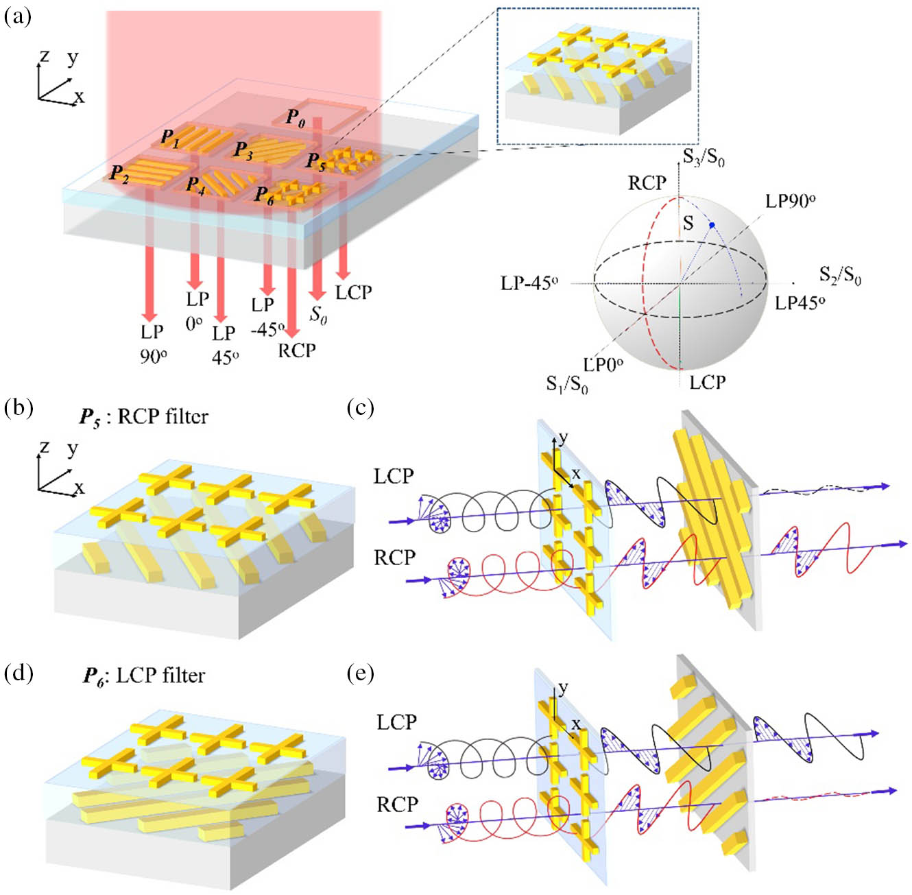
Fig. 2. Circular polarization filter design. (a) A schematic of the RCP filter. (b) Calculated amplitude and phase difference of electric field components of the transmitted light along two orthogonal arms of the crossbar metasurface (thickness 40 nm). The design parameters are as follows: L1=1.55  μm, L2=1.04  μm, Px=1.24  μm, Py=1.68  μm, and W=140  nm. (c) Transmission spectra of nanogratings for input light polarized perpendicularly (black solid line, polarization along 45° to the x-axis, i.e., the u-axis in the inset) or parallel (red solid line, along 45° to x-axis, i.e., v-axis in the inset) to the nanogratings (thickness 120 nm, period 200 nm, and duty cycle 50%) and the corresponding linear polarization extinction ratio (blue dashed line). (d) Transmission spectra of LCP (black) and RCP (red) light through the RCP polarization filter. The inset shows that RCP input is transmitted but LCP input is blocked. The design parameters for the crossbar antenna are as follows: L1=1.55  μm, L2=1.17  μm, Px=1.343  μm, Py=2.015  μm, and W=140  nm. The thickness of the oxide spacer layer is 350 nm. The nanogratings have the same design parameters as those in (c).

下载图片 查看原文

Fig. 3. Circular polarization filter performance and wavelength engineering. (a) The extinction ratio of an RCP filter (rCP=TRCP/TLCP) designed at wavelength 3.8  μm. Same design dimensions as Fig. 2(d). (b) Operation wavelength engineering of the CPL filters with different antenna length L1. The solid blue line is a linear fit of the data points (black squares) obtained with full-wave simulation (FDTD). More detailed information about the design parameters and simulation results is provided in Appendix B.

下载图片 查看原文

Fig. 4. Device fabrication process. (a) Major steps in device fabrication of CP polarization filter: (1) nanograting patterning on a sapphire substrate, (2) SiOx deposition by sputtering, and (3) crossbar antenna patterning. (b) An SEM image of nanogratings before SiOx deposition. (c) Top panel: an AFM image of a nanograting covered by SiOx. Bottom panel: the height profile along the white dashed line in the AFM image. (d) An SEM image of a fabricated mid-IR RCP filter.

下载图片 查看原文

Fig. 5. Experimental setup and measurement results of CP filters. (a) A schematic of the measurement setup for CP filter characterization. (b) Transmission spectra for a mid-IR RCP filter with RCP (red) and LCP (black) input. (c) The extracted CPER (rCP=TRCP/TLCP) for the RCP filter designed for an operation wavelength around 4 μm.

下载图片 查看原文

Fig. 6. Full-Stokes polarization measurements. (a) Schematic of the measurement setup. Unpolarized light from the FTIR is converted to polarized light with an arbitrary polarization state by adjusting the orientation of the standalone linear polarizer and the QWP. Then the light is transmitted through our device placed on a motorized stage and finally collected by the detector. (b)–(d) Polar plots and ellipse plots for polarization states A, C, and D in (e) (black circle: measured from polarization analyzer; red solid: measured from our Stokes parameter detector). (e) Measured Stokes parameters for nine polarization states (black circles: polarization states of input light; red squares: measured results with our device).

下载图片 查看原文

Fig. 7. Phase difference of the transmitted light along two orthogonal arms of the QWP metasurface with the length of the longer arm, L1=700, 900, 1045, 1160, 1300, 1360, 1500, and 1620 nm. Other design parameters are scaled accordingly.

下载图片 查看原文

Fig. 8. Geometric dimensions of the metasurface QWP with working wavelengths covering from NIR to MIR. L1 is the length of the longer arm along the y-axis, and L2 is the length of the shorter arm along the x-axis. Px is the period in the x-direction and Py is the period in the y-direction.

下载图片 查看原文

Fig. 9. Extinction ratio (rCP=TLCP/TRCP) for six LCP filters mentioned in Fig. 3(b). The other design parameters of the cross-bar antennas are as follows: L2=0.42, 0.58, 0.73, 0.82, 0.9, and 1.17 μm; and W=100, 100, 112, 127, 140, and 140 nm. The nanogratings have the same design parameters as those in Fig. 2(c). The thickness of the oxide spacer is 220 nm for the device at 1.6 μm and 350 nm for all the other designs.

下载图片 查看原文

Fig. 10. CPER for LCP filters with various spacer layer thicknesses. The other design parameters are the same as those used for the structure in Fig. 2(d).

下载图片 查看原文

Fig. 11. (a) Schematic for the MIR LCP filter with 0–200 nm lateral displacement along the y-axis. (b) CPER (rCP=TLCP/TRCP) for the MIR LCP filter with 0–200 nm lateral displacement along y-axis. The other design parameters are the same as those in Fig. 2(d).

下载图片 查看原文

Fig. 12. (a) Microscope image of the CPL filter (160  μm×160  μm) without an aperture. (b) Microscope image of the CPL filter with an input aperture (100 μm in diameter) and an aperture at the image plane (50  μm×50  μm).

下载图片 查看原文

Fig. 13. Stokes parameters measurement results for four polarization states, which correspond to the data points B, F, G, and H in Fig. 6(e). Black circles: measured with PA; red solid line: measured with our device. Blue arrows indicate the handedness of the polarization state.

下载图片 查看原文

Jing Bai, Chu Wang, Xiahui Chen, Ali Basiri, Chao Wang, Yu Yao. Chip-integrated plasmonic flat optics for mid-infrared full-Stokes polarization detection[J]. Photonics Research, 2019, 7(9): 09001051.

本文已被 2 篇论文引用
被引统计数据来源于中国光学期刊网
引用该论文: TXT   |   EndNote

相关论文

加载中...

关于本站 Cookie 的使用提示

中国光学期刊网使用基于 cookie 的技术来更好地为您提供各项服务,点击此处了解我们的隐私策略。 如您需继续使用本网站,请您授权我们使用本地 cookie 来保存部分信息。
全站搜索
您最值得信赖的光电行业旗舰网络服务平台!