Chinese Optics Letters, 2020, 18 (4): 040601, Published Online: Apr. 15, 2020
Applications of weakly-coupled few-mode fibers [Invited]  Download: 1105次
Figures & Tables
Fig. 1. Effective index difference between the first two modes, as a function of the effective area of the fundamental mode, with varying core radius for each core index, in (a) two-mode step-index fiber and (b) two-mode graded-index fiber. Step-index fiber with a 1.45 core index and a large range of core radius is plotted as the reference curve.
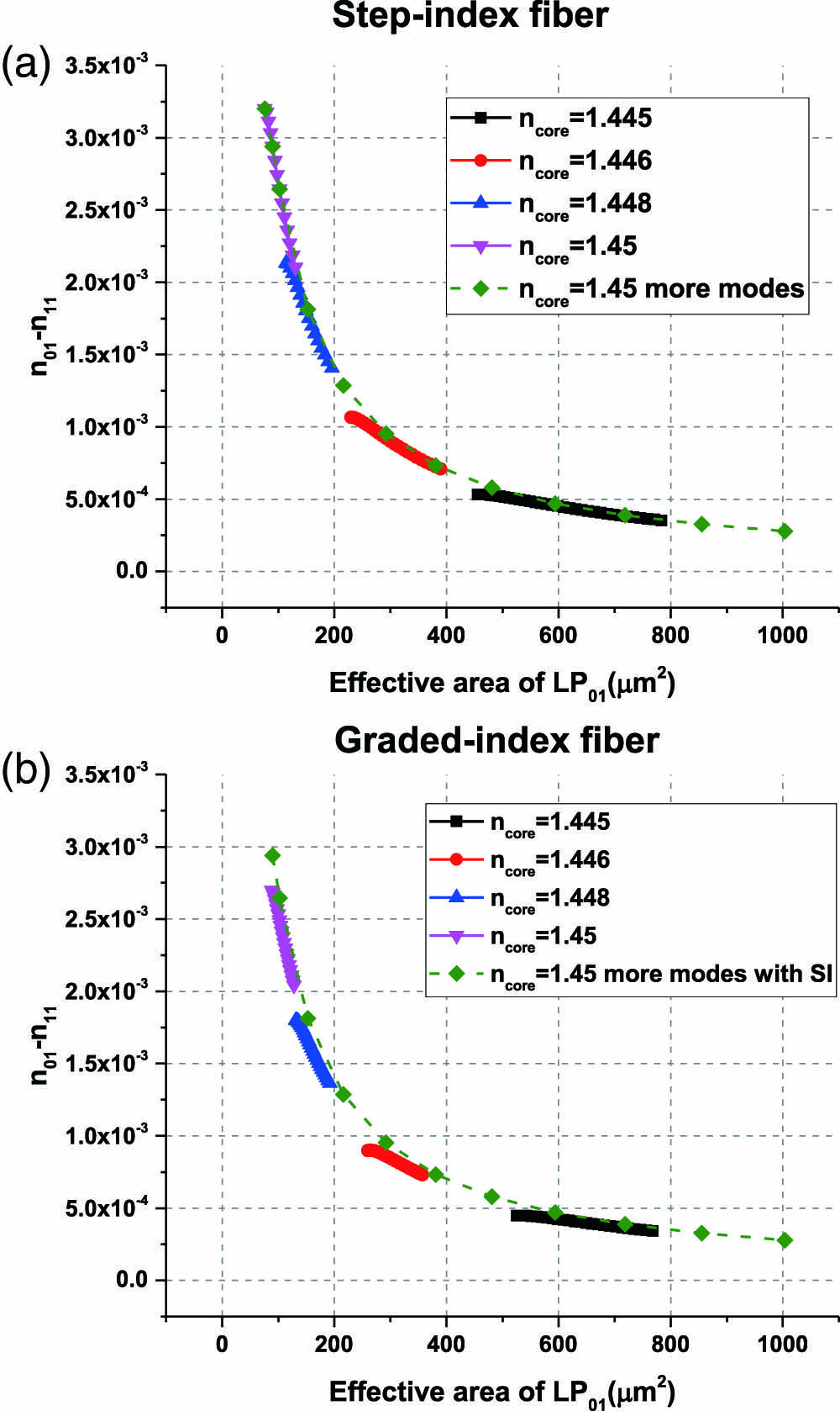
Fig. 2. (a) Effective index difference vs. effective area curve fitting for graded-index fiber. (b) The multiplication constant as a function of wavelength for SI or GRIN fibers with two or ten modes.

Fig. 3. (a) Index profiles for two-step SI fibers (high or low index for the inner step), a GRIN fiber with a trench, a triangular-index fiber, and a fiber corresponding to the reversed

Fig. 4. Fundamental mode profiles of (a) three-core fiber and (b) six-core fiber. (c) Corresponding curves of effective index difference vs. effective area.

Fig. 5. (a) Effective index difference of the 1st and 4th supermodes, and (b) the effective index difference of the first two supermodes vs. the effective area of 1st supermode, for different core distances.

Fig. 6. Setup for the

Fig. 7.

Fig. 8. (a) Refractive index profile of FMF, and effective indices of LP modes. Measured impulse response for (b) PL 1, (c) PL 2, and (d) PL 3. Each PL is spliced to a 20 km FMF. Reprinted from Ref. [19].

Fig. 9. Experiment setup for MGM transmission. BERT: bit error ratio tester; EDFA: erbium-doped fiber amplifier; VOA: variable optical attenuator; PC: polarization controller; PL: photonic lantern; PD: photodetector. Reprinted from Ref. [19].

Fig. 10. (a) Measured BERs as functions of transmitted power for detecting only one of the degenerate modes or both degenerate modes of the

Fig. 11. PON architectures using (a) an SMF with a power splitter and (b) an FMF with a mode multiplexer.


Fig. 13. Schematic of the six-mode-GPON system using a PL spliced to 20 km FMF for upstream transmission with commercial OLT and ONUs. OLT: optical line terminal; ONU: optical networking unit; PL: photonic lantern. Red line: 1490 nm transport; blue line: 1310 nm transport; gray line: bidirectional transmission. Reprinted from Ref. [21].

Fig. 14. Measured packet loss of 9 ONUs in the six-mode PON in 12 h. Reprinted from Ref. [21].

Fig. 15. Experimental setup for WDM transmission over an FMF link. The inset illustrates the generation of nonlinear cross talk due to four-wave mixing. Reprinted from Ref. [20].


Huiyuan Liu, He Wen, Guifang Li. Applications of weakly-coupled few-mode fibers [Invited][J]. Chinese Optics Letters, 2020, 18(4): 040601.


 PDF全文
PDF全文

