High Power Laser Science and Engineering, 2014, 2 (1): 010000e4, Published Online: Dec. 26, 2014
Controllability of intense-laser ion acceleration  Download: 701次
Figures & Tables
Fig. 1. (Color online) Concept of an example future laser ion accelerator. An intense laser illuminates a target, and a proton beam is generated at the ion source. The ion beam has a transverse divergence, and the proton energy is lower at the laser ion source. For ion cancer therapy as an example application, the proton energy must be 200–250 MeV to kill the cancer inside a human body. Therefore, further post-acceleration devices would be required to enhance the proton energy to achieve 200–250 MeV of proton energy and also to control the ion energy spectrum. In addition, ion collimators are also needed to suppress the ion beam divergence. In order to compress the ion beam longitudinally, a beam buncher may be required. All the components are realized by laser–target interactions in this example concept.
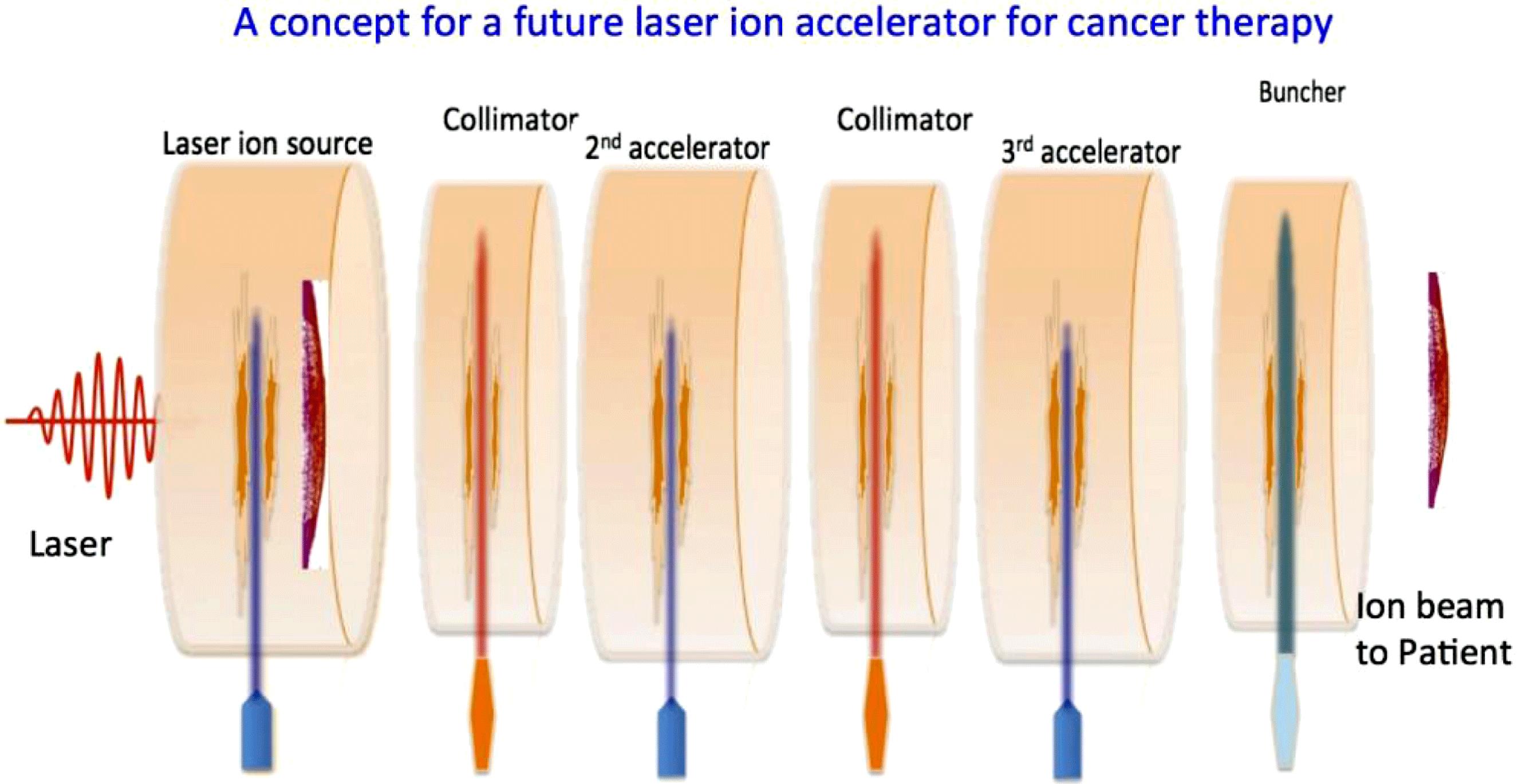
Fig. 2. Thin-foil targets: (a) a plain target, (b) a multihole target, and (c) the target structure used in this study. An intense short-pulse laser gives electrons its energy, and the hot electrons are accelerated. The electrons form a strong electric field, and the protons are accelerated. The target surface reflects the laser. In the multihole target, the holes transpiercing the target help to enhance the laser–proton energy conversion efficiency. We employ a double-layer target which consists of Al and H. The Al layer has a linear density gradient in  . The calculation area is
  in the longitudinal direction and
  in the transverse direction. The hole diameter is
  , and the hole distance is also
  .
.

Fig. 3. Distributions of the proton kinetic energy at 500 fs: (a) the plain target and (b) the multihole target. The proton kinetic energies become significantly high in the multihole target.

Fig. 4. Total-energy histories of the protons and electrons (a) in the plain target and (b) in the multihole target. The solid lines and the dotted lines are the histories of the electrons and the protons, respectively.

Fig. 5. Energy spectra of the hot electrons at 80 fs. The solid line presents the distribution in the plain target and the dotted line shows the distribution in the multihole target.

Fig. 6. Histories of the total number of the protons over 0.1 MeV in the plain target and the multihole target. The solid line shows the history in the plain target and the dotted line shows the history in the multihole target. The proton number in the multihole target becomes about 2.7 times larger than that in the plain target at 500 fs.

Fig. 7. The intense laser interacts with the hydrogen gas plasma, and protons are accelerated at the target rear surface by TNSA and magnetic vortex acceleration. The longitudinal electric fields, which contribute the ion acceleration at (a)  fs and (b) 180 fs, and the magnetic fields at (c)
  fs and (d) 180 fs. At the same time, the laser generates high-energy electrons inside the target. A transverse magnetic field is also formed along the channel in the laser–plasma interaction. During the increase phase of the magnetic field an inductive longitudinal electric field is created.

Fig. 8. A collimation device for the ion beam. The Al structured target is illuminated by an intense laser. The fine structure absorbs the laser energy efficiently, and generates high-energy electrons. The electrons move around the target, and at the right-hand side the electric field is created normally to the target surface. The transverse field is generated by the electrons and collimates the proton beam.

Fig. 9. The transverse electric field is successfully generated, and reduces the proton divergence.

Fig. 10. Divergence angle distributions for the original proton beam and for the collimated beam. The collimation device reduces the proton transverse divergence successfully.

Fig. 11. A bunching device illuminated by an intense laser. The structured Al target absorbs the laser efficiently, and a strong electric field is generated to accelerate the ion beam tail in this specific case.

Fig. 12. (Color online) At the bunching device the TNSA acceleration field is generated (see (a)–(c)). The pre-accelerated proton beam is introduced to the bunching field (see (d) and (g)). With the longitudinal velocity divergence, the proton beam is elongated (see (e) and (f)). When the bunching device is used, the proton beam velocity divergence is reduced significantly, as shown in (h) and (i).

Fig. 13. The pre-accelerated proton beam is introduced to the bunching device. At  the proton beam has the velocity divergence. With the longitudinal velocity divergence, the proton beam is elongated (see (a)). When the bunching device is used, the proton beam velocity divergence is reduced well as shown in (b).

Fig. 14. The conceptual diagram for post-acceleration in the laser–plasma interaction. The ions generated from the laser ion source are accelerated by several-stage post-acceleration. We employ a near-critical density plasma target, which consists of hydrogen. In this example, four-stage ion acceleration is performed.

Fig. 15. The histories of the maximum proton energy from the first acceleration to the fourth post-acceleration. The maximum proton energy is remarkably accelerated by the four-stages acceleration. The maximum proton energy is finally about 254.0 MeV in the fourth post-acceleration at 450 fs.

Fig. 16. Acceleration electric fields averaged over the laser one cycle along the center line of the plasma target in the longitudinal direction. The black solid line is  at
at  fs and the grey dotted line is at
  fs in the fourth post-acceleration. (b) The proton spatial distributions at
  fs, 90 fs, 160 fs, 240 fs, and 450 fs. The color shows the energy of the protons. (c) The energy distributions at
  fs, 90 fs, 160 fs, 240 fs, and 450 fs for the protons existing in
  at 450 fs. The maximum proton energy finally reaches 254 MeV in the fourth post-acceleration at 450 fs.

Fig. 17. Energy spectra of protons in the fourth post-acceleration. The dotted lines are the input ion beam to the fourth stage, and the solid lines are the output ion beam. Figures present all the ions, including the scattered ions transversely, and the inset figure shows the high-energy core part of the beam ions located in  . The core part of the beam ion is useful for practical purposes.

Shigeo Kawata, Toshihiro Nagashima, Masahiro Takano, Takeshi Izumiyama, Daiki Kamiyama, Daisuke Barada, Qing Kong, Yan Jun Gu, Ping Xiao Wang, Yan Yun Ma, Wei Ming Wang, Wu Zhang, Jiang Xie, Huiran Zhang, Dongbo Dai. Controllability of intense-laser ion acceleration[J]. High Power Laser Science and Engineering, 2014, 2(1): 010000e4.


 PDF全文
PDF全文

