Photonics Research, 2018, 6 (4): 040000A1, Published Online: Jul. 10, 2018
Dispersive non-Hermitian optical heterostructures
Figures & Tables
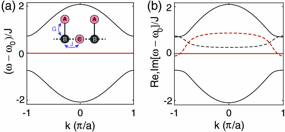
Fig. 2. Absorption coefficient | α 1 | Δ ϵ α 2 = 0.2 α 2 = 2 α 2 = 5

Fig. 3. (a) Reflectance [R ( L ) ( ω ) R ( R ) ( ω ) Θ = 15 ° ω 01 = 1 PHz ω 02 = 1.2 PHz γ 1 = 0.067 PHz γ 2 = 0.14 PHz | α 1 | = 20.86 α 2 = 2 ϵ 01 = 2 ϵ 02 = 3.22 d g = d l = 500 nm S

Fig. 4. (a) Reflectance [R ( L ) ( ω ) R ( R ) ( ω ) Θ = 0 ° ω = 0.92 PHz ω 01 = 1 PHz ω 02 = 2 PHz γ 1 = 0.067 PHz γ 2 = 0.14 PHz α 1 = 2 ϵ 01 = 2 ϵ 02 = 2.2 d g = d l = 500 nm α 2 = 92.3 α 2 = 156.5 Θ = 0 ° Θ = 30 ° Θ = 60 ° d g = 500 nm

Fig. 5. (a) Geometry of non-Hermitian periodic stack. (b), (c) Geometries of non-Hermitian random stacks. (d), (e) Transmittance of TM wave through the stacks incident at ω = 0.92 PHz Θ = 0 ° Θ = 60 ° d g = d l = 250 nm d g 1 = d g 3 = d l 1 = d l 3 = 200 nm d g 2 = d l 2 = 100 nm d g 1 = d g 2 = 200 nm d l 1 = d l 2 = d g 3 = 100 nm d l 3 = 300 nm 4 . The range of frequencies in (d) and (e) corresponding to loss dominated system is gray shaded.

Fig. 6. Eigenvalues of the S ω 01 = ω 02 = ω = 1 PHz γ 1 = γ 2 = 0.067 PHz ϵ 01 = ϵ 02 = 2 d g = d l = 500 nm Θ = 0 ° ω 01 = 1 PHz ω 02 = 2 PHz γ 1 = 0.067 PHz γ 2 = 0.14 PHz α 1 = 2.4 ϵ 01 = 2 ϵ 02 = 2.2 d g = d l = 500 nm ω = 2.65 PHz Θ = 0 ° λ 1 λ 2

O. V. Shramkova, K. G. Makris, D. N. Christodoulides, G. P. Tsironis. Dispersive non-Hermitian optical heterostructures[J]. Photonics Research, 2018, 6(4): 040000A1.


 PDF全文
PDF全文

