中国激光, 2021, 48 (5): 0501003, 网络出版: 2021-03-12
掺镱光纤-固体高功率超短脉冲放大研究进展  下载: 1928次特邀综述
Research Progress of Ytterbium-Doped Fiber-Solid High-Power Ultrashort Pulse Amplification
图 & 表
图 1. 全保偏(all-PM)NALM锁模掺镱光纤振荡器的结构示意图[26]
Fig. 1. Structural diagram of all-PM Yb-doped NALM mode-locked fiber oscillator[26]
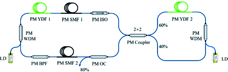
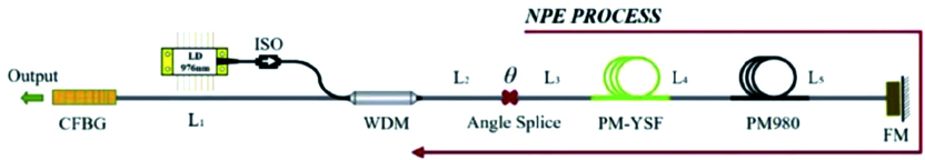
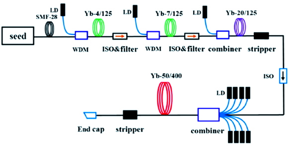
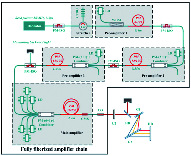

图 6. 大间距PCF啁啾脉冲放大系统的示意图[42]
Fig. 6. Diagram of large-pitch PCF chirped-pulse amplification system [42]
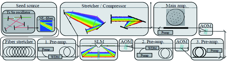

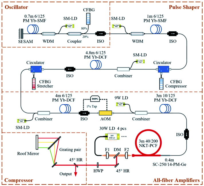
图 9. 全保偏NALM锁模光纤振荡器示意图及1.03 μm皮秒CPA系统示意图[48]。(a)全保偏NALM锁模光纤振荡器示意图;(b)1.03 μm皮秒CPA系统示意图
Fig. 9. Diagram of all-polarization-maintaining NALM mode-locked fiber oscillator, and diagram of 1.03 μm picosecond CPA system[48]. (a) Diagram of all-polarization-maintaining NALM mode-locked fiber oscillator; (b) diagram of 1.03 μm picosecond CPA system
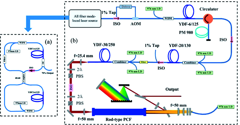
图 10. 国产PCF放大实验装置示意图。(a)全光纤振荡器和脉冲展宽器示意图;(b)双包层光纤放大器示意图;(c)国产PCF主放大器示意图
Fig. 10. Diagrams of experimental setups of domestic PCF amplification. (a) Diagram of all-fiber oscillator and pulse stretcher; (b) diagram of double-cladding fiber amplifier; (c) diagram of domestic PCF main amplifier
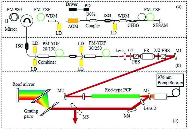
图 11. 锁模振荡器的光谱图和自相关曲线。(a)光谱图;(b)自相关曲线
Fig. 11. Spectrum and autocorrelation curve of mode-locked oscillator. (a) Spectrum; (b) autocorrelation curve
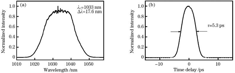
图 12. 初级预放大后的输出光谱和无源光纤展宽后的脉冲形状。(a)初级预放大后的输出光谱;(b)无源光纤展宽后的脉冲形状
Fig. 12. Output spectrum after primary pre-amplification, and pulse shape broadened by passive fiber. (a) Output spectrum after primary pre-amplification; (b) pulse shape broadened by passive fiber

图 13. 30/250 μm掺镱光纤放大器的输出光谱和脉冲形状。(a)输出光谱;(b)脉冲形状
Fig. 13. Output spectrum and pulse shape of 30/250 μm ytterbium doped fiber amplifier. (a) Output spectrum; (b) pulse shape
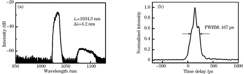
图 14. 主放大级输出功率与泵浦功率的关系,以及主放大后输出脉冲经过压缩后的自相关曲线。(a)主放大级输出功率与泵浦功率的关系;(b)主放大后输出脉冲经过压缩后的自相关曲线
Fig. 14. Output power as a function of pump power in main amplification stage, and autocorrelation trace of compressed output pulse after main amplification. (a) Output power as a function of pump power in main amplification stage; (b) autocorrelation trace of compressed output pulse after main amplification

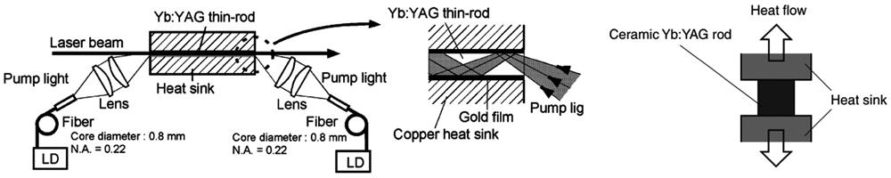
图 16. 单晶光纤中心泵浦功率吸收比率示意图,以及普通装配技术和Taranis模块中单晶光纤泵浦端面的温度分布[56].(a)单晶光纤中心泵浦功率吸收比率示意图;(b)普通装配技术和Taranis模块中单晶光纤泵浦端面的温度分布
Fig. 16. Evolution of fraction of pump power absorbed in central part of SCF, and temperature distribution of SCF pumped facet in Taranis module and conventional mounting technique[56]. (a) Evolution of fraction of pump power absorbed in central part of SCF; (b) temperature distribution of SCF pumped facet in Taranis module and conventional mounting technique
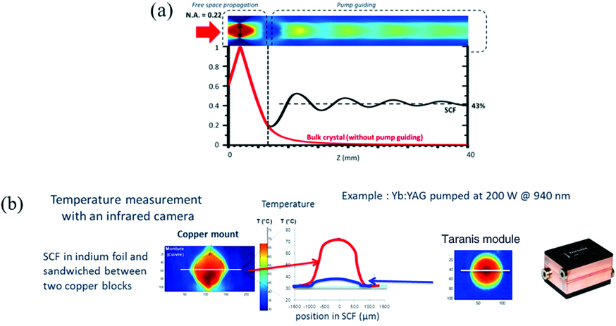
图 17. Yb∶YAG细棒和多通碟片放大系统示意图[61]
Fig. 17. Diagram of Yb∶YAG thin rod and multi-pass disk amplification system[61]
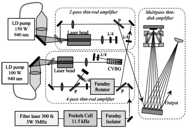
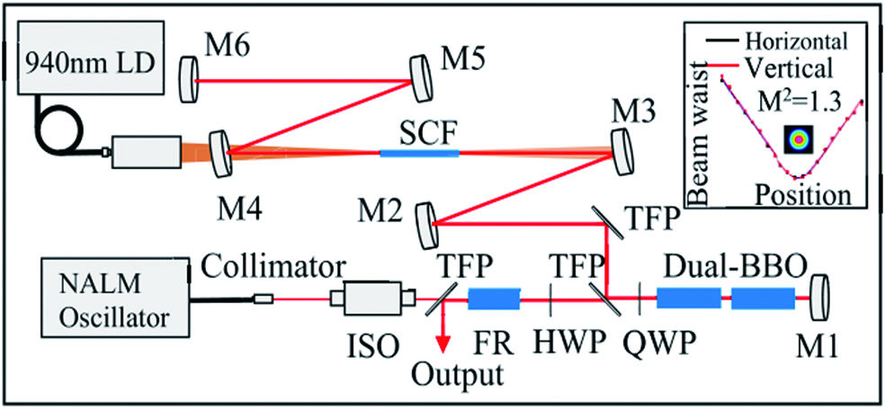
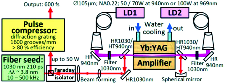
图 20. 具有光纤前端和自由空间Yb∶YAG放大器的CPA系统的示意图[74]
Fig. 20. Diagram of CPA system with fiber frontend and free-space Yb∶YAG amplifier[74]
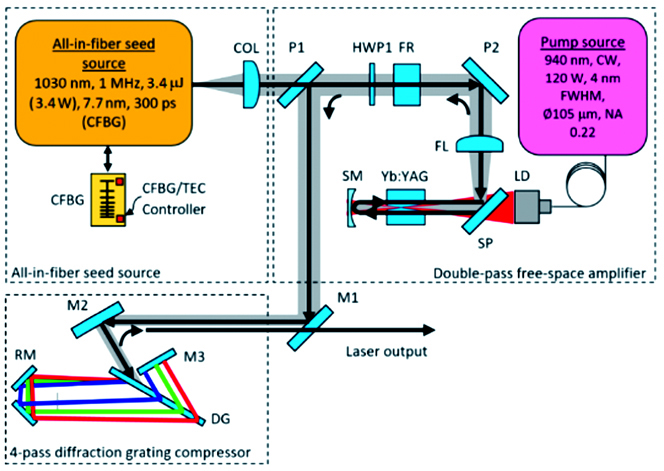
图 21. 掺镱光纤和Yb∶YAG细棒混合MOPA系统的示意图[76]
Fig. 21. Diagram of hybrid MOPA system with Yb-fiber and Yb∶YAG thin-rod[76]
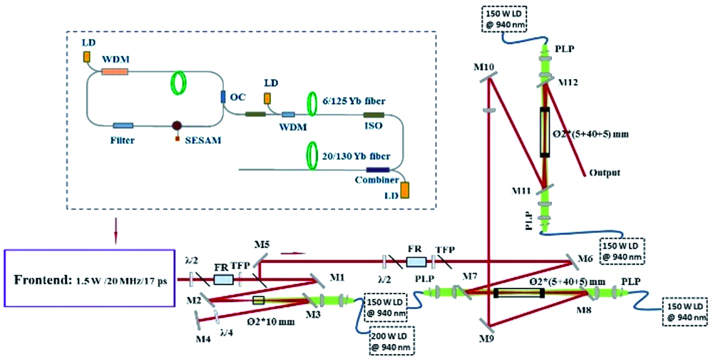
图 22. 侧面及端面角度的直接水冷时侧抛晶体棒捕获ASE的路径示意图,ASE会减小在晶体棒中的环形区域存储的激光增益[77]
Fig. 22. Diagrams of optical path of sidecast crystal rod trapping ASE for direct water cooling at side and end angles. ASE decreases laser gain stored in annular region of crystal rod[77]
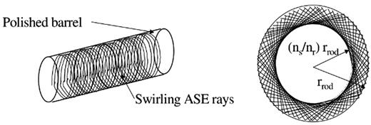
图 23. 两级双端泵浦的Φ2×(5+40+5) mm的Yb∶YAG键合细棒放大器示意图,以及第一级和第二级放大器的输出功率。(a)两级双端泵浦的Φ2×(5+40+5) mm的Yb∶YAG键合细棒放大器示意图;(b)第一级放大器的输出功率;(c)第二级放大器的输出功率
Fig. 23. Diagram of two-stage double-end pumped Φ2×(5+40+5) mm Yb∶YAG bonding thin rod amplifier, and output powers of first stage amplifier and second stage amplifier. (a) Diagram of two-stage double-end pumped Φ2×(5+40+5) mm Yb∶YAG bonding thin rod amplifier; (b) output power of first stage amplifier; (c) output power of second stage amplifier
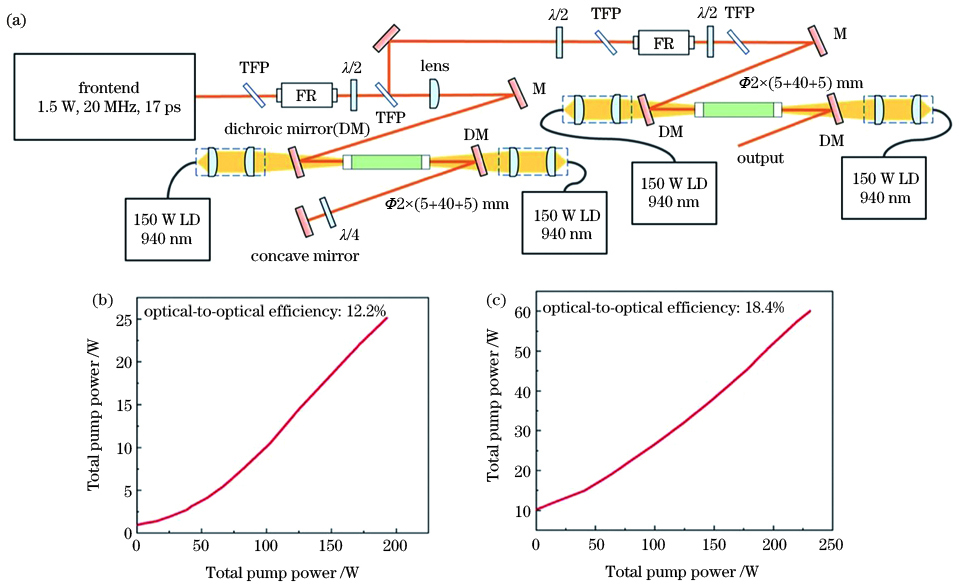
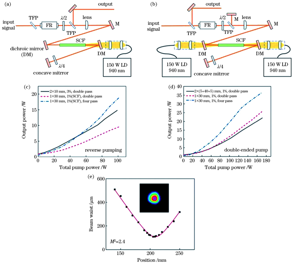
图 24. 反向泵浦双通放大、双端泵浦四通放大示意图,反向泵浦、双端泵浦时不同规格Yb∶YAG晶体的输出功率,以及单晶光纤双端泵浦四通放大的光束质量因子。(a)反向泵浦双通放大示意图;(b)双端泵浦四通放大示意图;(c)反向泵浦时不同规格Yb∶YAG晶体的输出功率;(d)双端泵浦时不同规格Yb∶YAG晶体的输出功率;(e)单晶光纤双端泵浦四通放大的光束质量因子
Fig. 24. Diagrams of reverse-pumped double-pass amplification and dual-end-pumped four-pass amplification, output powers of Yb∶YAG crystals of different specifications during reverse pumping and dual-end-pumped, and beam quality factor of SCF dual-end-pumped four-pass amplification. (a) Diagram of reverse-pumped double-pass amplification; (b) diagram of double-ended pumped four-pass amplification; (c) output power of Yb∶YAG crystals of different specifications during reverse pumping; (d) output power of
徐岩, 彭志刚, 程昭晨, 石宇航, 王贝贝, 王璞. 掺镱光纤-固体高功率超短脉冲放大研究进展[J]. 中国激光, 2021, 48(5): 0501003. Yan Xu, Zhigang Peng, Zhaochen Cheng, Yuhang Shi, Beibei Wang, Pu Wang. Research Progress of Ytterbium-Doped Fiber-Solid High-Power Ultrashort Pulse Amplification[J]. Chinese Journal of Lasers, 2021, 48(5): 0501003.


 PDF全文
PDF全文

