制冷型中波红外偏振成像光学系统设计
Design of cooled medium-wave infrared polarization imaging optical system
1 南京莱斯电子设备有限公司,江苏 南京 210014
2 中国电子科技集团第二十八研究所,江苏 南京 210007
3 31105部队,江苏 南京 210000
图 & 表
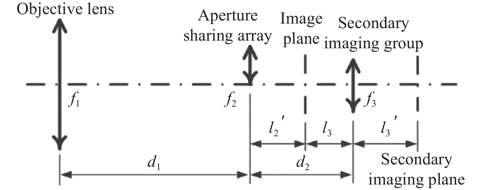
图 1. Schematic diagram of initial structure of aperture sharing medium-wave infrared polarization imaging optical system分孔径中波红外偏振成像光学系统初始结构示意图
Fig. 1.
下载图片 查看原文
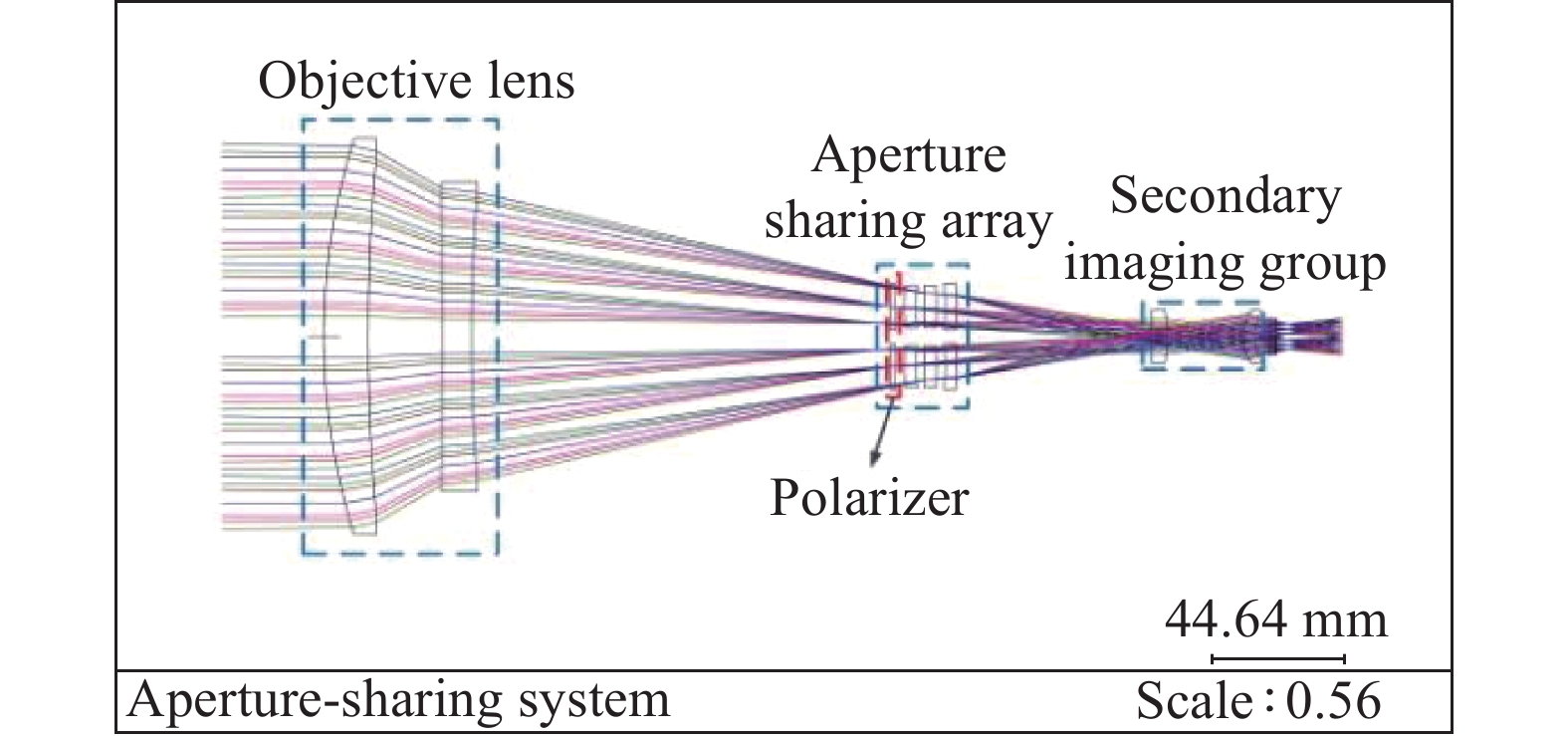
图 2. 2D layout of aperture sharing medium-wave infrared polarization imaging optical system分孔径中波红外偏振成像光学系统二维布局图
Fig. 2.
下载图片 查看原文
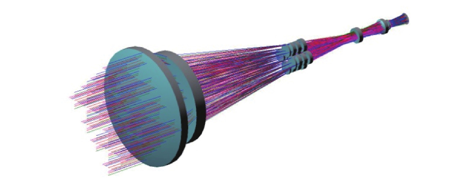
图 3. 3D layout of aperture sharing medium-wave infrared polarization imaging optical system分孔径中波红外偏振成像光学系统三维布局图
Fig. 3.
下载图片 查看原文
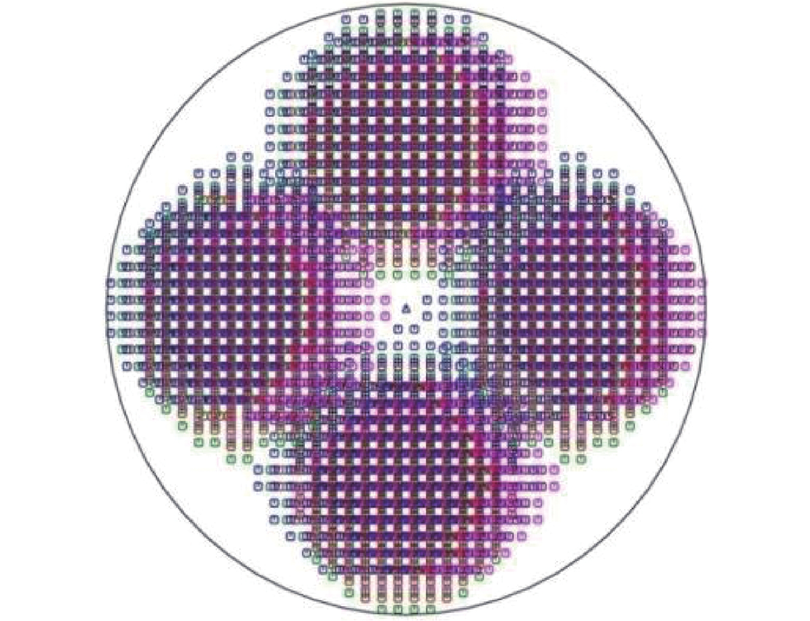
图 4. Results of the pupil distribution in the medium-wave infrared polarization imaging optical system中波红外偏振成像光学系统入瞳处分孔径结果
Fig. 4.
下载图片 查看原文
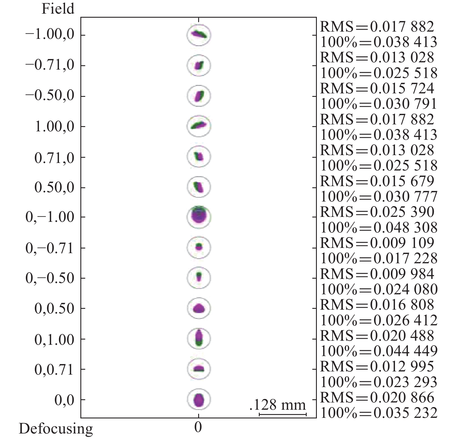
图 5. Spot diagram of single channel of aperture sharing medium-wave infrared polarization imaging optical system分孔径中波红外偏振成像光学系统单通道点列图
Fig. 5.
下载图片 查看原文
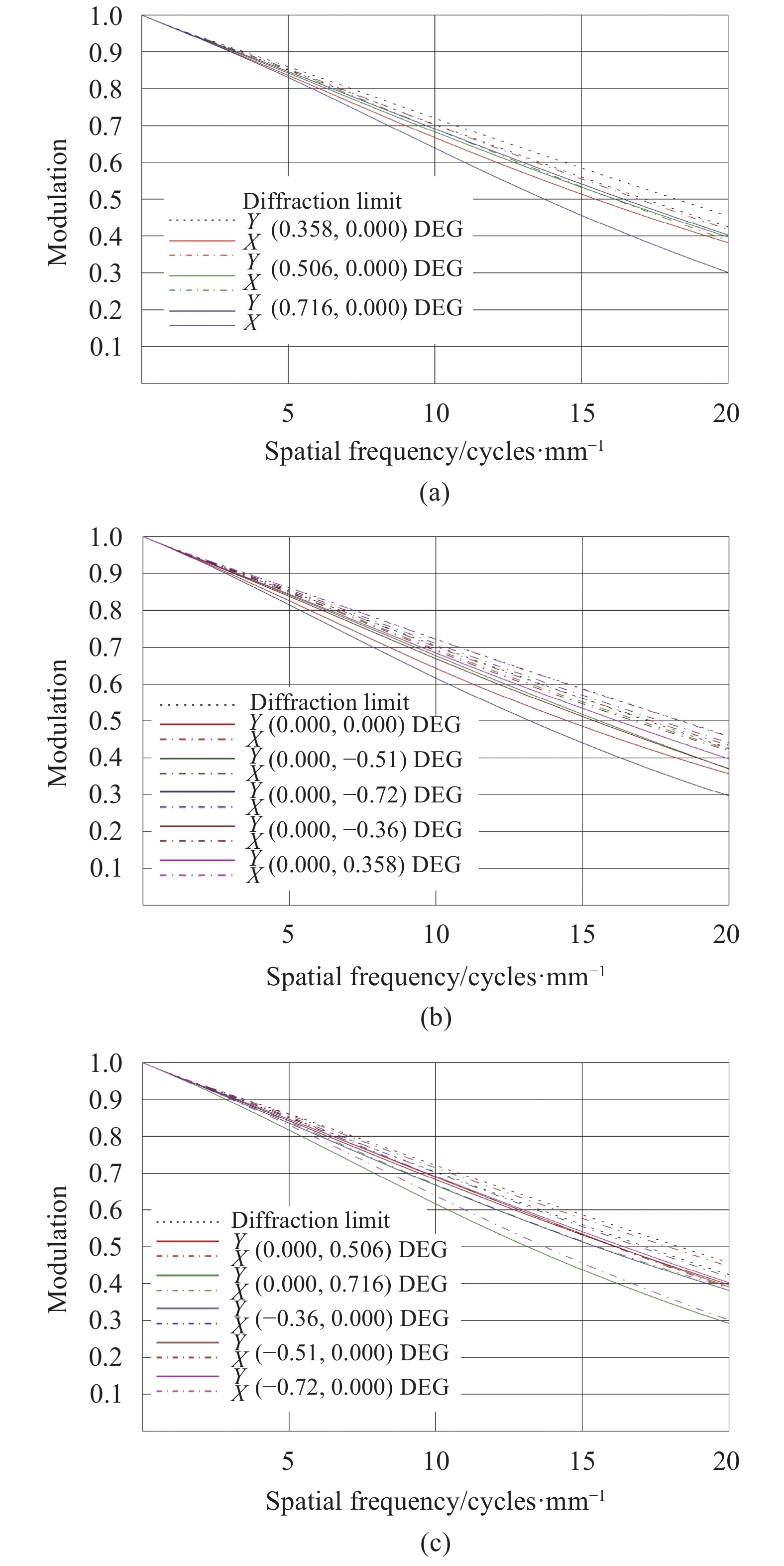
图 6. MTF of single channel of aperture sharing medium-wave infrared polarization imaging optical system分孔径中波红外偏振成像光学系统单通道MTF图
Fig. 6.
下载图片 查看原文
图 7. OPD of single channel of aperture sharing medium-wave infrared polarization imaging optical system分孔径中波红外偏振成像光学系统单通道像差曲线
Fig. 7.
下载图片 查看原文
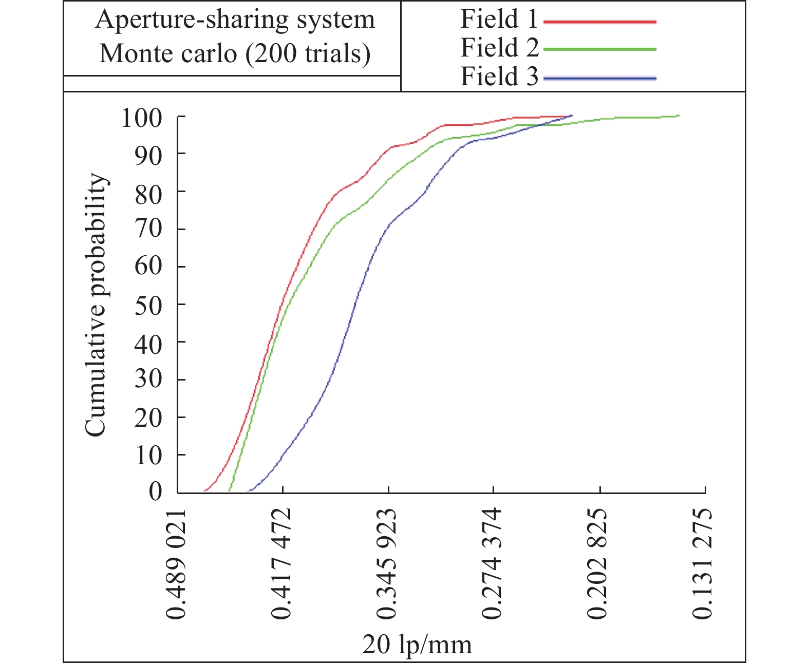
图 8. Statistical results of tolerance analysis公差分析统计结果
Fig. 8.
下载图片 查看原文
图 9. Schematic diagram of cold reflection ray-tracing冷反射光线追迹图
Fig. 9.
下载图片 查看原文
表 1
Realization and characteristics of polarization imaging
偏振成像实现方式及特点
Table1.
| Imaging method | Advantages | Disadvantages | | Time-sharing polarization imaging | Rotating polarizer | Simple system structure; Low cost; Small energy
loss; High spatial resolution
| Poor real-time performance; Poor
reliability of moving parts
| | Electrically tuned LCD | Simple system structure; Small size; Easy to adjust;
High spatial resolution
| Poor real-time performance; Large energy loss | | Simultaneous polarization imaging | Amplitude sharing | Good real-time performance;
High spatial resolution
| Complex structure; High adjustment requirements;
Big size; Large energy loss; High cost
| | Aperture sharing | Good real-time performance; Relatively
low cost; Compact structure
| Relatively complex structure;
Loss of spatial resolution
| | Focal plane sharing | Good real-time performance; Small size;
Compact structure; High integration
| High adjustment requirements; Instantaneous field of
view error; Loss of spatial resolution
|
|
查看原文
表 2
Parameters of the designed optical system
光学系统性能参数
Table2.
| Parameter | Value | | Wavelength/μm | 3.7-4.8 | | Focal length/mm | 240 | | F# | 6 | | Field/(°) | 1.15×0.92 | | Number of pixels | 320×256 | | Pixel size/μm2 | 30×30 |
|
查看原文
表 3
Comparison of aperture sharing medium-wave infrared polarization imaging optical system
中波红外分孔径偏振成像光学系统比较
Table3.
| Structure of polarization imaging optical system | Number of optical elements per channel | Transmittance estimation | | 注:根据当前红外透镜镀膜工艺水平以及线偏振片的性能,透过率估算过程中取红外透镜单面透过率为98%,偏振片透过率为85% | 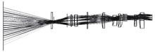 | 12 lenses 1 polarizer | 52.4% |  | 10 lenses 1 polarizer | 56.8% | 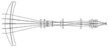 | 13 lenses 1 polarizer | 50.2% |  | 12 lenses 2 wave plates 1 polarizer | < 48.3% |
|
查看原文
表 4
Tolerance limits
公差分配表
Table4.
| Surface | Tolerance | | Test plate fit | 1-16 | 2 | | Irregularity | 1-16 | 0.5 | | Thickness/mm | 1-16 | 0.02 | | Decenter/mm | 1-16 | 0.02 | | Tilt/(″) | 1-4 | 30 | | 5-16 | 40 |
|
查看原文
表 5
Result of cold reflection analysis
冷反射分析结果
Table5.
| Surface | Clipping aperture | YNI/mm | I/IBAR | | 1 | 13 (R) | 1.726 | 3.85 | | 2 | 13 (R) | −2.12 | 1.924 | | 3 | 13 (R) | −2.206 | 2.024 | | 4 | 13 (R) | −0.623 | 1.283 | | 5 | 13 (R) | −0.395 | 1.578 | | 6 | 13 (R) | −0.393 | 1.578 | | 7 | 13 (R) | 0.486 | −1.887 | | 8 | 13 (R) | 0.096 | −0.382 | | 9 | 13 (R) | −0.95 | 4.703 | | 10 | 13 (R) | −0.416 | 1.845 | | 11 | 13 (R) | −0.471 | 2.253 | | 12 | 13 (R) | −0.919 | 5.709 | | 13 | 20 (R) | 0.169 | 2.086 | | 14 | 20 (F) | 0.043 | −0.249 | | 15 | 20 (R) | 0.693 | 2.647 | | 16 | 20 (F) | 0.167 | −1.241 |
|
查看原文
刘星洋, 翟尚礼, 李靖, 汪洋, 苗锋, 杜瀚宇, 邹超凡. 制冷型中波红外偏振成像光学系统设计[J]. 红外与激光工程, 2021, 50(2): 20200208. Xingyang Liu, Shangli Zhai, Jing Li, Yang Wang, Feng Miao, Hanyu Du, Chaofan Zou. Design of cooled medium-wave infrared polarization imaging optical system[J]. Infrared and Laser Engineering, 2021, 50(2): 20200208.


 PDF全文
PDF全文
