The laser diode-pumped solid state laser is developing rapidly and a variety of arrangements are employed. In the thickness direction of the planar waveguide (PW), the optical field distribution is dominated by the guided wave effect. Therefore, it can largely reduce the degradation of the beam quality caused by a temperature gradient. As a format of the laser active medium, PWs offer several advantages over their bulk counterparts[1] such as strong optical confinement providing high gain and low threshold, excellent thermal management characteristics, and a great degree of versatility of the pump arrangement[2–6" target="_self" style="display: inline;">–6]. For a typical large mode PW core size of , when the laser power reaches 10 kW, the light intensity is only . It is much lower than for the kilowatt-class fiber laser in which the core diameter is 20 μm. In addition, the length of the PW is two orders of magnitude smaller than a typical fiber laser, so it will not cause an obvious nonlinear effect. Compared to the for the 10 kW slab amplifier, the PW high laser brightness can guarantee a very high extraction efficiency.
The master-oscillator power-amplifier (MOPA) configurations with PW geometries are of special interest in scaling the average power output because of the high width-to-height aspect ratio of their gain media[7,8]. The first use of a Yb:YAG PW amplifier for ultrafast pulse amplification by combining it with a high-average-power Yb:KYW femtosecond oscillator with an output average power of 50 W has been reported[9]. The output power of 16 kW is obtained from an MOPA PW configuration[10], which indicates that the PW is a flexible alternative gain material employed in an MOPA configuration. In 2006, Raytheon used the 200 μm Yb:YAG as the gain medium and the output reached 16 kW when the injection power was 100 W. The electro-optical efficiency was above 20%, but no beam quality was reported. Raytheon claims that there are no technical barriers to be reached at the 100 kW or even the megawatt level, and in 2012 Raytheon announced that it had completed a power and an electro-optical efficiency greater than 30%[11].
Rare earth ion-doped YAG ceramics have become a more promising candidate host material for the laser gain medium, as novel nanotechnology has made it possible to synthesize highly homogeneous transparent laser ceramics[12–20" target="_self" style="display: inline;">–20]. A buried waveguide in Nd:YAG ceramic media by the direct femtosecond-laser writing technique with an output energy of 2.8 mJ for the pump with pulses of 13.1 mJ energy has been reported[21]. Therefore, such a compact waveguide geometry holds the greatest potential for increasing the laser output power while maintaining single-mode operation.
An MOPA system based on a composite YAG/Nd:YAG/YAG transparent ceramic PW is presented in this Letter. By using quasi-continuous-wave (QCW) pumping at a 100 Hz repetition rate, an output pulse energy of 327 mJ is achieved with a pulse width of 250 μs. The beam quality at the highest output energy is measured to be about . The spontaneous emission is detected to analyze the influence of amplified spontaneous emission (ASE) and parasitic oscillation (PO).
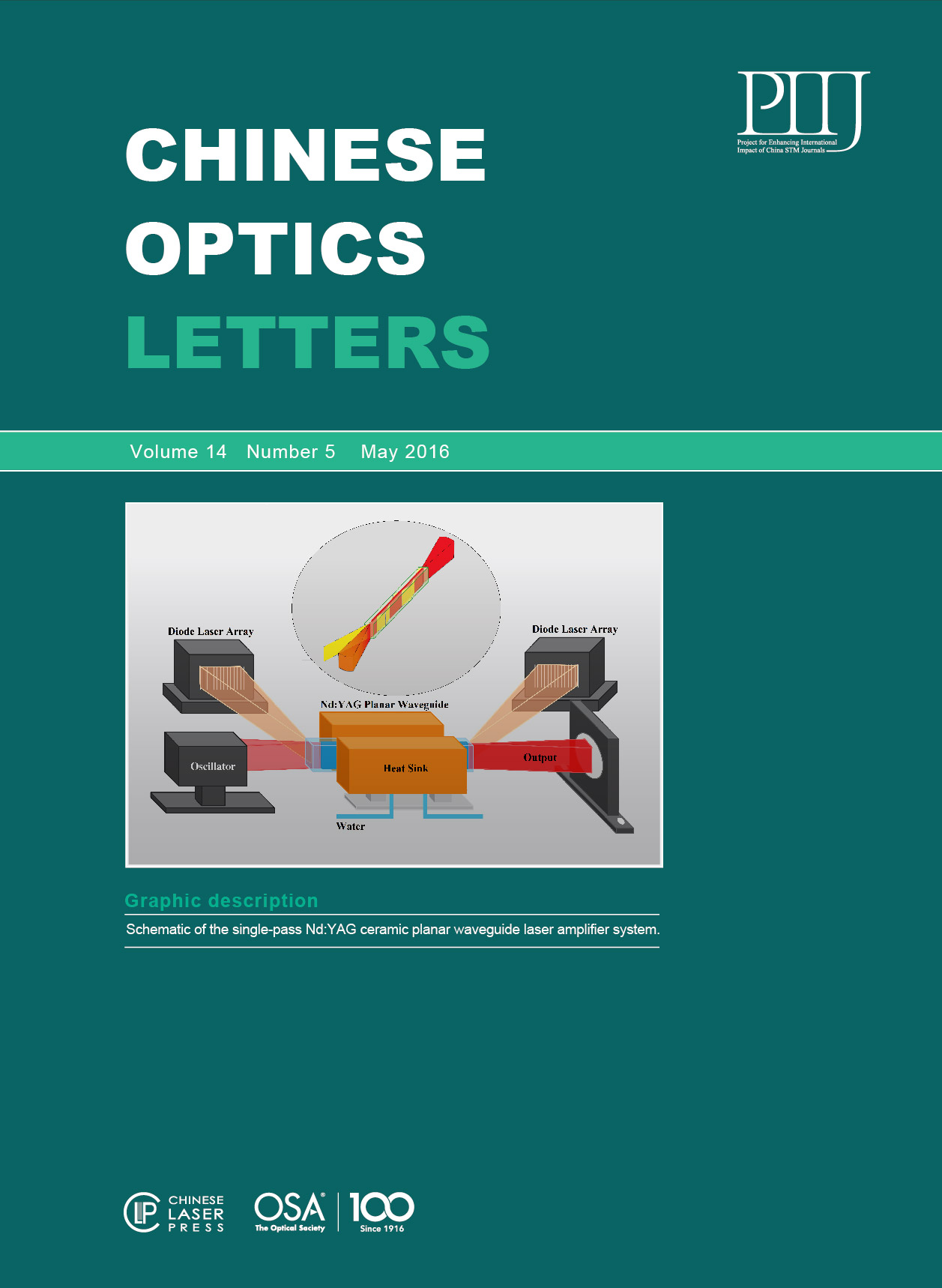
The experimental configuration of the single-pass Nd:YAG PW MOPA system is shown in Fig. 1. The system consists of the following four parts: the oscillator, the isolator, the beam shaping and coupling system, and the amplifier. The oscillator as a seed source is a two-rod Nd:YAG laser. The two rods have the same dimensions of 85 mm long and 4 mm diameter. An optical imaging system with a magnification of one and a 90° polarization rotator placed between the rods, imaging the facing principle planes of both rods onto each other and exchanging the radial and tangential polarization states between the rods, compensates for birefringence and bifocusing. The oscillator is followed by an optical isolator to prevent feedback from the amplifier. The beam sizes of the seed signal are controlled to ensure the optimal matching between the signal and the pump distribution.
Fig. 1. Schematic of the Nd:YAG ceramic PW amplifier.
下载图片 查看所有图片
Fig. 2. Nd:YAG PW consisting of a 100 μm-thick 1.5 at. % Nd:YAG core with 450 μm-thick YAG claddings. Heat is removed from the two largest surfaces.
下载图片 查看所有图片
A ceramic Nd:YAG PW fabricated by the nonaqueous tape casting and solid-state reactive sintering method[22] is used in our experiments. The waveguide has outside dimensions of 10 mm wide by 60 mm long by 1 mm high, consisting of two 450 μm-thick undoped YAG cladding layers and a Nd:YAG core with a concentration of 1.5 at. % (in Fig. 2). The core layer is Nd:YAG with a refractive index of 1.8182. The inner cladding layer is non-doped YAG with a refractive index of 1.8172; the corresponding numerical aperture . The core layer thickness that can satisfy the single-mode condition is 8.9 μm. There are 11 modes; for the weak conduction case (), TE and TM are almost degenerate.
The largest facets of the PW are high-reflection (HR) coated for the wavelength 808 nm, and the two end facets are precision polished and are anti-reflection (AR) coated at 808 nm. To remove the heat, the PW is mounted between two copper water-cooled heat sinks.
Our system uses double-ended pumping from two 20-bar diode laser stacks. Each stack emitted at 808 nm with a maximum output pulse energy of 676 mJ. The smile control is smaller than 1 μm. In order to prevent the nonabsorbed pump to be incident upon the opposite diode stack, the two diode stacks have the different angles of 30° and 35° with respect to the PW. The pump beam is formatted to a 4 mm radius in the unguided plane ( axis) near the center of the PW, and focused down to a 300 μm radius in the guided plane ( axis) at the PW input facet. The fast axis is focused into the waveguide by a cylindrical lens of focal length and the slow axis is collimated by two cylindrical lenses of focal lengths and .
In the experiment, a digital pulse generator with double-output channels is used to separately trigger the pumps for the oscillator and the amplifier.
The oscillator in the QCW modes gives out a maximum energy of 136.2 mJ at the output mirror. The beam quality measurement of the master oscillator is shown in Fig. 3. The beam quality factor values are measured to be 2.8 and 3.4 at the maximum pump energy. The far field of the oscillator laser mode is nearly Gaussian with a diameter of around 4 mm (at ).
Fig. 3. Beam quality measurement of the master oscillator.
下载图片 查看所有图片
Figure 4 shows the output energy from the amplifier versus the (absorbed) double-ended and single-ended pump energy curves corresponding to the laser operation with various input signal pulse energies.
Fig. 4. Output laser energy versus the (a) double-ended and (b) single-ended pump energy.
下载图片 查看所有图片
As can be seen from these curves (when double-ended pumping), when the input signal pulse energy is 10.2, 21.3, 30.8, 42.2, 51, and 61.9 mJ, the maximum output energy extracted from the PW reached a saturation level of about 76.5, 130.2, 172.1, 214, 242, and 272.2 mJ, respectively. With the input signal pulse energy increasing to 82.2 mJ, the output energy increases nearly linearly with the pumping energy as the amplifier is sufficiently extracted. The maximum output pulse energy is 327 mJ, with the optical-to-optical efficiency of 56% and signal gains of . The output laser energy versus single-ended pumping energy curves has a similar trend. When the input signal energy reaches 44.3 mJ or a higher energy of 65.3 and 87 mJ, the output energy increases linearly with the pumping energy and reaches the maximum output pulse energy of 173.8, 206.7, and 238.2 mJ, respectively. The optical-to-optical efficiency is 71% (near the theoretical limit) [Fig. 4(b)]. When the input signal pulse energy is 1.26, 5.3, 10.8, and 25.3 mJ, a saturation energy of about 14.0, 38.1, 66.2, and 122.3 mJ is obtained, respectively. The data show that the saturation limit tends to be dependent on the input signal energy. We believe that it is a series of POs and ASEs that leads to low efficiency. By increasing the input signal energy, the ASE and amplification saturation can be efficiently restrained.
The spontaneous emission is detected without an input signal to analyze the influence of ASE and PO. Three PINs were used to image the signal wave, two of which had the 10 nm FWHM bandpass filter centered at 1064 and 808 nm, respectively. The temporal trace of the signal pulses is displayed in Fig. 5. The red, green, and yellow lines represent the spontaneous emission, pump beam. and drive current signal of the diode stacks, respectively. We regard the pump drive current signal (yellow line) as the pulse time reference.
Fig. 5. Temporal trace of a signal pulse at the drive current of (a) 50, (b) 53, (c) 60, and (d) 110 A when double-ended pumped. The red, green, and yellow lines represent the spontaneous emission, pump beam, and current signal of the diode stacks, respectively.
下载图片 查看所有图片
As can be seen, when the waveguide is double-ended pumped, the PO and ASE of 1064 nm can easily take place in the pump current of 53A (when single-ended pumped it is 74A) and then increase markedly with the pump current, which acted as a reason for the energy extraction degradation of the 1064 nm laser. In addition, the input signals’ intensity decreases slowly after being amplified because of the existence of inversed upper level particles.
Output laser energy versus pump drive current curves is shown in Fig. 6. We think that a departure from the expected behavior caused by PO occurred to the right of lines AB and CD. Lines AB and CD cut the axis at points A and C, corresponding to pump currents of around 55 and 80 A, respectively. These critical current values represent the thresholds of PO and ASE, which match the results of 53 and 74 A from the fluorenscence measurement well (Fig. 5), corresponding to the pump energy of about 93 and 84 mJ. This explains the leveling off of the output energy versus pump input energy curve when the amplifier is completely saturated.
Fig. 6. Output laser energy versus the (a) double-ended and (b) single-ended pump drive current. Departure from the expected behavior caused by PO occurred to the right of lines AB and CD.
下载图片 查看所有图片
The PO and ASE are found to be in the paths illustrated in Fig. 7. It is found that the intensity of the PO and ASE in positions 1–4 is much higher than those in positions 5–6.
Fig. 7. Paths in which the PO and ASE are found.
下载图片 查看所有图片
The luminescence effect (positions 1–4) has been observed in the 70.2°–84.4° range (). Consequently, according to the laws of reflection and refraction, the angle of the emitted light (in Fig. 8) has been calculated to be in the 31.2°–33.2° range, and angle in the 56.8°–58.8° range. The critical angles of the largest facet and end facet are and , respectively. The angle is greater than , and is approximately equal to but slightly less than . Therefore, lights in the waveguide are reflected by the largest and end facets many times, and finally emitted from the end facets with the approaching critical angle. The luminescence effect in positions 5 and 6 is caused by a small reflection from the end facets of the waveguide. As a result, the PO and ASE have been found to be much higher on the paths (positions 1–4) than along the axis (positions 5 and 6). Furthermore, it has been proved that little oscillation is induced by reflection from other components. Therefore, the end facet chamfered to 10° is under consideration for suppressing PO and restricting ASE generation.
Fig. 8. Schematic diagram of fluorescence propagation.
下载图片 查看所有图片
The beam quality of the output laser is measured by a Spiricon laser beam analyzer at the maximum energy. When the laser worked at the maximum pulse energy output, the beam quality factor values of 2.6 and 7.3 were obtained in the guided and nonguided direction, respectively. Figure 9 illuminates the far-field laser beam profile of the intensity distribution. According to the beam profile, it is Gaussian in shape without sidelobes in the guided direction. Beam quality in the guided direction is much better than in the nonguided direction. Accordingly, in the future work, we will attempt to control the spatial mode in the nonguided direction.
Fig. 9. Two-dimensional far-field beam intensity distribution measured after amplification.
下载图片 查看所有图片
In conclusion, we demonstrate a QCW high-energy, high-beam-quality composite ceramic YAG/Nd:YAG/YAG PW MOPA laser system. At a repetition rate of 100 Hz and a pulse width of 250 μs, a maximum output pulse energy of 327 mJ is obtained with a beam quality factor of . The corresponding peak power is 1308 W. This is, to the best of our knowledge, the highest output energy with such a good beam quality reported to date for the ceramic Nd:YAG PW fabricated by nonaqueous tape casting and solid-state reactive sintering. In addition, we analyze the mechanism of the ASE phenomenon and think the reason is that high reflectivity of the heat sink interface causes the small angle of spontaneous emission light multiple reflections and thus obtains a strong ASE. At the same time, it is pointed out that increasing the light energy of the injected seed can effectively extract the energy storage and inhibit ASE. In the next experiment, we will use a single side welding heat sink of the waveguide laser medium to verify our analysis.
Jiao Liu, Lin Ge, Liwen Feng, Hao Jiang, Hua Su, Tangjian Zhou, Juntao Wang, Qingsong Gao, Jiang Li. Diode-pumped composite ceramic Nd:YAG planar waveguide amplifier with 327 mJ output at 100 Hz repetition rate[J]. Chinese Optics Letters, 2016, 14(5): 051404.


 double-ended and (b) single-ended pump energy.")
 50, (b) 53, (c) 60, and (d) 110 A when double-ended pumped. The red, green, and yellow lines represent the spontaneous emission, pump beam, and current signal of the diode stacks, respectively.")
 double-ended and (b) single-ended pump drive current. Departure from the expected behavior caused by PO occurred to the right of lines AB and CD.")


 PDF全文
PDF全文

