Chinese Optics Letters, 2021, 19 (2): 021201, Published Online: Dec. 18, 2020
Spatially modulated polarimetry based on a vortex retarder and Fourier analysis  Download: 744次
Figures & Tables
Fig. 1. Schematic of our experimental configuration. IS, integrating sphere; L, positive lens; P, polarizer; Q, quarter-wave plate; ZVHR, zero-order vortex half-wave retarder; A, analyzer.

Fig. 2. Typical measured results of linearly polarized light. (a) The recorded hourglass intensity image of horizontal linearly polarized light. (b) A ring ROI cut from (a). (c) The normalized intensity modulation curves as a function of azimuth angle
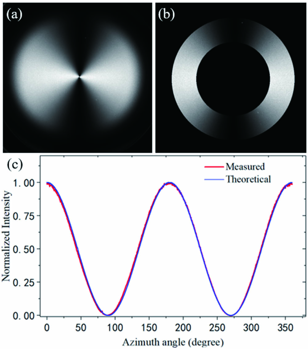
Fig. 3. Experimental results measured from multiple regularly varied SOPs. (a) Experimental (black star, S1; red circle, S2; blue triangle, S3) and theoretical (black line, S1; red line, S2; blue line, S3) Stokes parameters corresponding to different SOPs. (b) Experimental (red star) and theoretical (blue line) data shown on a Poincaré sphere.
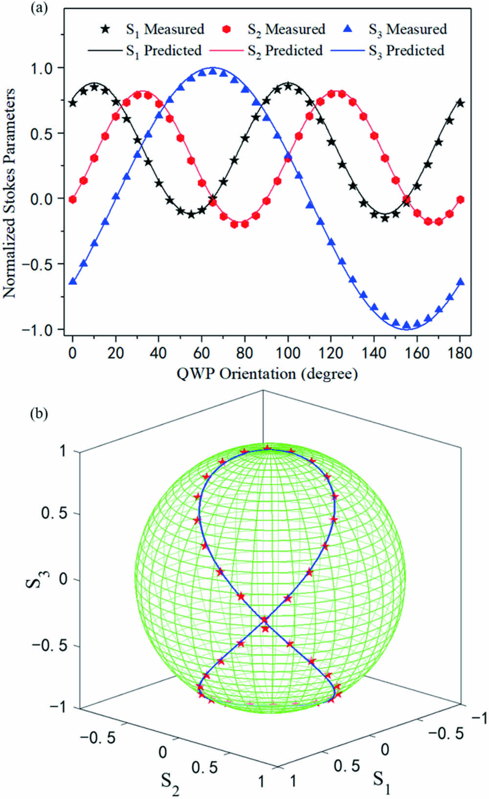
Table1. Measured Results of Incident Beams with Some Particular Polarization States
| |||||||||||||||||||||||||||||||||||||||||||||||||||||||||||||||||||||||||||||||||||||||||||||||||||||||||||||||||
Chao Gao, Bing Lei. Spatially modulated polarimetry based on a vortex retarder and Fourier analysis[J]. Chinese Optics Letters, 2021, 19(2): 021201.


 PDF全文
PDF全文

