Chinese Optics Letters, 2017, 15 (12): 120603, Published Online: Jul. 18, 2018  

Pulse reference-based compensation technique for intensity-modulated optical fiber sensors Download: 713次

Author Affiliations
1 Academy of Ocean Science and Engineering, National University of Defense Technology, Changsha 410073, China
2 College of Optoelectronics Science and Engineering, National University of Defense Technology, Changsha 410073, China
Abstract
We propose a compensation technique based on pulse reference for intensity-modulated optical fiber sensors that can compensate the power fluctuation of the light source, the change of optical components transmission loss, and the coupler splitting ratio. The theoretical principle of this compensation technique is analyzed and a temperature sensor based on fiber coating-covered optical microfiber is carried out to demonstrate the compensation effect. The system noise is measured to be 0.0005 dB with the temperature sensitivity reaching 0.063 dB/°C, and the output drift is 0.006 dB in 2 h at room temperature. The output shows a slight variation (0.0061 dB) when the light source and the common light path suffer a 3 dB attenuation fluctuation.

Intensity-modulated optical fiber sensors (IM-OFSs) are one of the most important and earliest developed OFSs for their simplicity, using inexpensive light sources, and potential low cost. In past decades, IM-OFS have been well studied to detect several types of physical quantities such as displacement[1], temperature[2,3], bending[4], strain[5], magnetic field intensity[6], and others[7,8]. However, owing to directly using optical intensity as the information carrier, IM-OFSs have the problem that the output might be affected by the fluctuation of the light source, the change of optical components transmission loss, and the coupler splitting ratio, as well as other factors with time and external perturbations. Many compensation techniques were proposed to solve this problem: the light source negative-feedback compensation technique[9], the light split compensation technique[3,10], the twin-receiving-fiber compensation technique[11], the dual-wavelength compensate technique[12], the network-based compensation technique[13], and the neural-network compensation technique[14]. The performances of the IM-OFSs were improved[1519" target="_self" style="display: inline;">19] but there still exist some unavoidable problems for the compensation techniques mentioned above. For example, though the light split compensation technique can compensate the fluctuation of the light source, it cannot solve the splitting ratio fluctuation caused by the optical splitter itself. The network-based compensation technique can avoid the splitting ratio fluctuation problem, but it introduces more optical components transmission loss fluctuation problems.

In this Letter, we propose a compensation technique based on pulse reference. This compensation technique can compensate the power fluctuation of the light source, the change of optical components transmission loss, and the coupler splitting ratio, while at the same time keeping the structure simple and the design flexible for a wide application range. Another advantage of this compensation technique is that it is completely compatible with optical time division multiplexing system, which can integrate a large number of sensors and decrease the cost of per sensor. After the explanation of this technique, an optical microfiber temperature sensor was carried out to demonstrate the good compensation effect of this technique.

The schematic diagram of the pulse reference-based compensation technique is shown in Fig. 1. A light pulse emitted by the light source is divided into two light pulses (signal pulse and reference pulse) by the 2×2 fiber optic coupler. These two pulses will both come back again to the coupler after being transmitted and reflected by their respective fiber and reflector. Then the detector will receive two pulses and transform them into electrical signals. The signal processing unit is responsible for converting them into digital signals and analyzing these signals.

Fig. 1. Schematic diagram of the pulse reference-based compensation technique.

下载图片 查看所有图片

The time delay Δt between the signal pulse and reference pulse depends on the relative length of the sensing fiber and delay fiber. For the purpose of distinguishing these two pulses in the time domain, Δt is supposed to be much longer than the laser pulse width. The output voltage of the signal pulse Us and the reference pulse Ur can be expressed as Us=RI0α0(1C)αsrsαsC,Ur=RI0α0Cαrrrαr(1C).

Here, R is the responsibility of the detector; I0 is the initial light intensity; α0, αs, αr are the transmittance of the common optical path, sensing fiber, and reference fiber; C is the coupling ratio of the 2×2 fiber optic coupler; rs and rr are the reflectance of the first and second reflector, respectively.

We define a measurement parameter, relative loss (RL) of the sensing part, from Eqs. (1) and (2) as follows: RL=10·log(UsUr)=10·log(rsαs2rrαr2).

It is obvious that RL is unrelated to the initial light pulse intensity I0, the coupling ratio C, the transmittance of the common optical path α0, and the photodetector responsibility R. That means, theoretically, RL will not be influenced by those parameters’ fluctuation.

So, if we keep αr and rr stable and design αs or rs sensitive to a certain physical quantity (temperature, displacement, refractive index, salinity, etc.), we can use this system to detect it.

To demonstrate the effect of the pulse reference-based compensation technique, a temperature-sensing experiment based on a fiber coating-covered optical microfiber was carriedout with this techniqueout, as shown in Fig. 2.

Fig. 2. Schematic diagram of the temperature OFS based on the fiber coating-covered optical microfiber with the pulse reference-based compensation technique.

下载图片 查看所有图片

A 1.55 μm wavelength semiconductor pulsed laser (Connet, Pulsed Fiber Laser Source, VSLC-1559-M-P) with 250 ns pulse width and 10 kHz repeat frequency was used as the light source. The laser line width is about 40 nm. The relative length between the sensing fiber and the delay fiber was set to be 60 m, providing a 600 ns time delay. Two Faraday rotating mirrors (FRMs) were used as reflectors. The sensing head, which was fabricated utilizing an optical microfiber covered by a fiber coating, was placed in a temperature chamber. The pulses were detected by the photodetector (New Focus, Model 2053) with an 80 MHz bandwidth. The amplitudes of the signal pulses and reference pulses were converted into digital data by data acquisition card NI PXIe-5122 with a 100M sample rate. All data was dealt by LabVIEW software in a computer to get the average voltage value of each pulse for further calculation.

The sensing optical microfiber used in this experiment was drawn from a conventional single-mode fiber (SMF) with the modified flame-brush method[20]. The diameter of the drawn optical microfiber is 2μm, as its microscope photograph shows in Fig. 3(a). The fiber coating fabricated by The Chinese North Coating Research Center is a good material for the encapsulation of optical microfiber, with its refractive index reaching 1.42. Ultraviolet light was used to cure the fiber coating after the optical microfiber was embedded into it. A photograph of the optical microfiber covered by a fiber coating is shown in Fig. 3(b).

Fig. 3. (a) The microscope photograph of the drawn optical microfiber. (b) The photograph of the optical microfiber covered by fiber coating

下载图片 查看所有图片

Because of the optical microfiber’s excellent optical properties, such as large evanescent field, compact size, and low loss, it can be utilized as a good alternative material for sensing. When light passes through the optical microfiber, there is a large fraction of power propagating outside the optical microfiber as an evanescent field that makes it very sensitive to the change of external physical quantities[21]. The absorption coefficient of the fiber coating changes accordingly when the external temperature changes, altering the transmittance of the fiber coating-covered optical microfiber in the meantime[3]. In this experiment, αr, rs, and rr remain relatively stable due to the usage of temperature insensitive optical fiber and FRM.

For convenience we choose a specific RL0 as a benchmark and just observe the variation of RL of sensing part as δRL=RLRL0.

The external temperature of the sensing head was controlled by the temperature chamber. The RL decreases from 0.54dB at 10°C to 3.69dB at 60°C throughout the experiment. The RL value at 10℃ is chosen to be the benchmark RL0. So, according to Eq. (4), we obtain δRL in different temperatures, as shown in Fig. 4. δRL and temperature show an approximate linear relationship and the temperature sensitivity is 0.063dB/°C, with its R-squared value better than 0.99, according to linear fitting. The system noise is measured to be 0.0005 dB in a short time at any constant temperature, as an example in 25°C is shown in Fig. 5.

Fig. 4. δRL versus temperature.

下载图片 查看所有图片

Fig. 5. Fluctuation of δRL in 5 min at 25℃.

下载图片 查看所有图片

The system noise is much lower than that of conventional IM-OFSs[3,2124" target="_self" style="display: inline;">24], and also allows the minimum detectable temperature variation to reach 0.008°C for this temperature sensor.

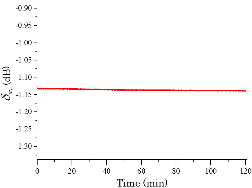
Long-term stability is also a key index for a temperature sensor. The δRL variation was monitored for 2 h at room temperature, about 25°C. As shown in Fig. 6, the output drift of δRL is measured to be only 0.006 dB.

Fig. 6. Output drift of δRL in 2 h at room temperature, about 25℃.

下载图片 查看所有图片

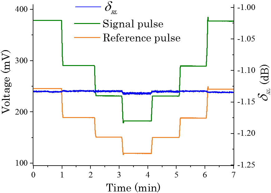
To evaluate the influence of the fluctuation of the light source and the change of optical components transmission loss and coupler loss, an attenuator was inserted between the isolator and the fiber optic coupler to simulate those influences at room temperature. By setting the attenuator, the light intensity of the incident pulse decreased by 1 dB per minute until the loss reached 3 dB and then gradually returned to its original value in the next few minutes. We detected δRL and output voltages of signal pulse and reference pulse in real time. As is shown in Fig. 7, δRL keeps constant with about a 0.0061 dB change when 3 dB attenuation is set by the attenuator, which is quite small. The variation might result from the existence of bias, which leads to the difference between the measured values and theoretical values of Us and Ur. But this result can still demonstrate the good effect of our compensation technique.

Fig. 7. (Color online) Fluctuation of δRL output in different attenuations.

下载图片 查看所有图片

In conclusion, a compensation technique for IM-OFSs based on pulse reference is proposed in this Letter. A temperature sensing experiment using fiber coating-covered optical microfiber was designed and carried out to demonstrate the compensation effect. With this compensation technique, the system noise is only 0.0005 dB, much lower than that of conventional IM-OFSs. The sensitivity of the temperature sensor is 0.063dB/°C with its resolution reaching 0.008°C. The output changes slightly by 0.0061 dB when the attenuation of the light source and common light pulse reach 3 dB and the output drift is only 0.006 dB in two hours at room temperature, demonstrating the good compensation effect and long-term stability of this system.

The further improvement on this compensation effect can be done in terms of the polarization state, the laser line width, and the bias problem. The compensation technique also shows its potential in time division multiplexing and quasi-distributed sensing in the case of a suitable lightpath design. Our follow-up work will be carried out in these aspects.

References

[1] DongB.HaoE. J., J. Opt. Soc. Am. B28, 2332 (2011).JOBPDE0740-3224

[2] SilvaR. M.BaptistaJ. M.SantosJ. L.Lobo RibeiroA. B.AraújoF. M.FerreiraA. L.FrazãoO., Opt. Commun.291, 215 (2013).OPCOB80030-4018

[3] WeiZ.SongZ.ZhangX.YuY.MengZ., Chin. Opt. Lett.11, 110602 (2013).CJOEE31671-7694

[4] ZawawiM. A.O’KeeffeS.LewisE., Sensors13, 14466 (2013).SNSRES0746-9462

[5] MoscatoM.SchenaE.SaccomandiP.FrancomanoM.AccotoD.GuglielmelliE.SilvestriS., in IEEE Engineering in Medicine and Biology Society (2012), p. 5790.

[6] ZhengJ.DongX.ZuP.JiJ., Appl. Phys. Lett.103, 090601 (2013).APPLAB0003-6951

[7] DongW.WeiJ.WangX.KangZ.XuX., Chin. Opt. Lett.12, 6 (2014).CJOEE31671-7694

[8] ZhangH.FengL.HouY.SuS.LiuJ.LiuW.LiuJ.XiongJ., Chin. Opt. Lett.13, 080601 (2015).CJOEE31671-7694

[9] YangH.HaibaoL.XuT.LuoW., Laser Technol. 26, 453 (2002).

[10] YangH.HaibaoL.XuT.LuoW., in Instrument Technique and Sensor (2001).

[11] YuanL.PanJ.YangT.HanG., Sens. Actuators A36, 177 (1993).

[12] MurtazaG.SeniorJ. M., Opt. Commun.120, 348 (1995).OPCOB80030-4018

[13] JinX.LiaoY., Acta Opt. Sin.16, 1002 (1996).

[14] WangX., Acta Opt. Sin.22, 215 (2002).GUXUDC0253-2239

[15] GuoY.WangY., J. Phys. Conf. Ser.48, 892 (2006).JPCSDZ1742-6588

[16] LiC.ZhangX.ZhangP., in International Conference on Mechatronics and Automation (ICMA) (2011), p. 1861.

[17] VallanA.CasalicchioM. L.OliveroM.PerroneG., IEEE Trans. Instrum. Meas.61, 1377 (2012).IEIMAO0018-9456

[18] GuoY.WangY.JinM., Optik125, 126 (2014).

[19] BrambillaG., J. Opt.12, 043001 (2010).

[20] LouJ.WangY.TongL., Sensors14, 5823 (2014).SNSRES0746-9462

[21] DongB.HaE., J. Opt. Soc. Am. B28, 2332 (2011).JOBPDE0740-3224

[22] DongX.ShaoL.FuH.TamH.LuC., Opt. Lett.33, 482 (2008).OPLEDP0146-9592

[23] AbadS.AraújoF. M.FerreiraL. A.SantosJ. L.LópezamoM., Appl. Opt.42, 5040 (2003).APOPAI0003-6935

[24] ZhouJ.WangY.LiaoC.YinG.JunH.BingS., in Asia Communications and Photonics Conference (2014).

Qiang Bian, Zhangqi Song, Yuzhong Chen, Xueliang Zhang. Pulse reference-based compensation technique for intensity-modulated optical fiber sensors[J]. Chinese Optics Letters, 2017, 15(12): 120603.

引用该论文: TXT   |   EndNote

相关论文

加载中...

关于本站 Cookie 的使用提示

中国光学期刊网使用基于 cookie 的技术来更好地为您提供各项服务,点击此处了解我们的隐私策略。 如您需继续使用本网站,请您授权我们使用本地 cookie 来保存部分信息。
全站搜索
您最值得信赖的光电行业旗舰网络服务平台!