Chinese Optics Letters, 2020, 18 (5): 052501, Published Online: Apr. 29, 2020
Switchable microwave photonic filter using a phase modulator and a silicon-on-insulator micro-ring resonator  Download: 754次
Figures & Tables
Fig. 1. Schematic diagram of the proposed microwave photonic filter. TLS, tunable laser source; PC, polarization controller; PM, phase modulator without a polarizer; MRR, micro-ring resonator; PD, photodetector; VNA, vector network analyzer.
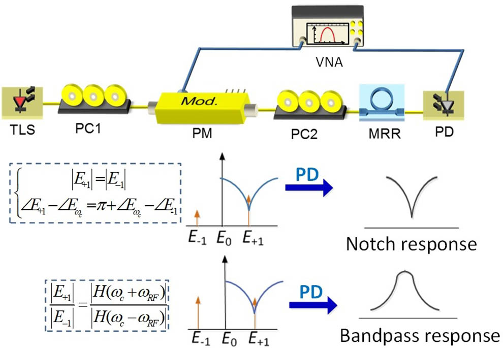
Fig. 2. Normalized magnitude and phase response of the MRR. Inset: the MRR used in the experiment.

Fig. 3. (a)–(c) Measured optical spectra of the optical signal output from the chip by adjusting the PC2. (d) The calculated relationship between the power ratio of the

Fig. 4. Measured beat signal spectra of the light output from the chip by adjusting PC2. Inset: the corresponding optical sideband spectra.

Fig. 5. Normalized frequency response of the MPF (a) band-stop filter and (b) band-pass filter (solid blue line, measured results; red dash line, simulated results). The optical spectra of the modulated signal at the MPFs’ center frequency: (c) band-stop; (d) band-pass.


Simin Li, Rong Cong, Zhengqian He, Tianliang Wang, Fangzheng Zhang, Shilong Pan. Switchable microwave photonic filter using a phase modulator and a silicon-on-insulator micro-ring resonator[J]. Chinese Optics Letters, 2020, 18(5): 052501.


 PDF全文
PDF全文

