基于微波光子的可重构变频移相信号产生  下载: 1143次
Generation of Reconfigurable Frequency-Conversion Signals with Full-Range Phase Shift Based on Microwave Photonics
1 空军工程大学信息与导航学院, 陕西 西安 710077
2 空军通信士官学校, 辽宁 大连 116600
3 中国空间技术研究院西安分院, 陕西 西安 710077
图 & 表
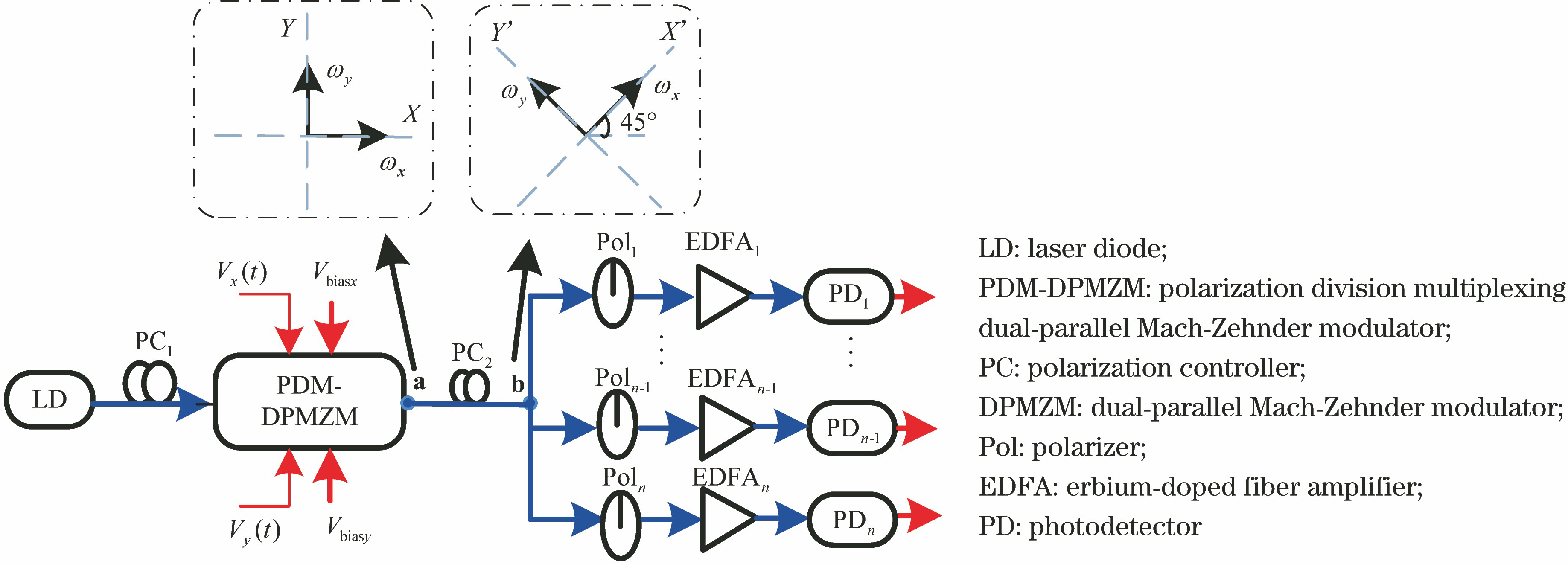
图 1. 基于PDM-DPMZM的二倍频或上/下变频多通道移相信号生成方案结构图
Fig. 1. Schematic diagram of the proposed frequency-doubled signal generation and frequency up-conversion or frequency down-conversion signal generation with full range phase shift
下载图片 查看原文
图 2. 不同功能下PDM-DPMZM的微波信号输入与直流偏置情况以及对应的输出光谱示意图。(a)二倍频移相;(b)上变频移相;(c)下变频移相;(d)三种情况下不同器件输出的光谱示意图
Fig. 2. RF input and DC biases of PDM-DPMZM under different phase-shift functions, and corresponding output spectrum diagram. (a) Frequency-doubled signal with phase shift; (b) frequency up-converted signal with phase shift; (c) frequency down-converted signal with phase shift; (d) output spectra for different components
下载图片 查看原文
图 3. 基于PDM-DPMZM的多通道多频段变频移相信号生成方案结构图
Fig. 3. Schematic diagram of the proposed multiband frequency-conversion signal generation with full range phase shift in multichannel
下载图片 查看原文
图 4. 多通道多频段变频移相信号生成时PDM-DPMZM的微波信号输入与直流偏置情况以及不同光边带组合示意图。(a) PDM-DPMZM的微波信号输入与直流偏置情况;(b)组合一;(c)组合二
Fig. 4. RF input and DC biases during the generation of the multiband frequency-conversion signal with phase shift in multichannel, and combination of optical sidebands. (a) RF input and DC biases; (b) combination 1; (c) combination 2
下载图片 查看原文
图 5. 4种情况下PDM-DPMZM输出光谱图(左)与PD输出电谱图(右)。(a)二倍频移相信号产生情况下;(b)上变频移相信号产生情况下;(c)下变频移相信号产生情况下;(d)多通道多频段变频移相信号产生情况下
Fig. 5. Optical spectra (left) at the output of PDM-DPMZM and electric spectra (right) at the output of PD in four cases. (a) In the case of the frequency doubling operation; (b) in the case of the frequency up-conversion operation; (c) in the case of the frequency down-conversion operation; (d) in the case of the multiband frequency conversion in multichannel
下载图片 查看原文
图 6. 二倍频移相、上/下变频移相与多通道多频段变频移相不同通道生成信号波形图。(a)二倍频移相信号波形(10 GHz);(b)上变频移相信号波形(13 GHz);(c)下变频移相信号波形(1 GHz);(d)多通道多频段变频移相信号中通道一信号波形(16 GHz);(e)多通道多频段变频移相信号中通道二信号波形(7 GHz);(f)多通道多频段变频移相信号中通道三信号波形(1 GHz)
Fig. 6. Waveforms of phase tuned signals in the case of the frequency doubling operation, frequency up-conversion and down-conversion operation and waveforms of phase tuned signals in different channels of multiband frequency conversion. (a) Waveforms of phase tuned frequency doubled signal (10 GHz); (b) waveforms of phase tuned frequency up-converted signal (13 GHz); (c) waveforms of phase tuned frequency down-converted signal (1 GHz); (d) waveforms of phase tuned signals in channel 1 of multiband freq
下载图片 查看原文
图 7. 二倍频及上/下变频移相信号生成与多通道多频段变频信号生成时不同相位下生成信号幅度变化。(a)二倍频及上/下变频移相信号生成时不同相位下生成信号幅度变化;(b)实现多通道多频段变频信号生成时不同相位下变频信号幅度变化
Fig. 7. Power variation of phase tuned signals under different conditions of frequency doubling, frequency up-conversion, frequency down-conversion and multiband frequency conversion. (a) Power variation under different conditions of frequency doubling, frequency up-conversion and frequency down-conversion; (b) power variation under generation of multiband frequency conversion signals
下载图片 查看原文
图 8. 生成上变频移相信号(13 GHz)时直流偏置点漂移对系统性能的影响。(a) 信号功率随直流偏置点漂移的变化;(b) USSR随直流偏置点漂移的变化
Fig. 8. Effect of DC points drift on system performance during the generation of frequency up-converted signal (13 GHz). (a) Power variation with the DC points drift; (b) USSR variation with the DC points drift
下载图片 查看原文
图 9. 生成多频段变频移相信号的一路信号(7 GHz)时直流偏置点漂移对系统性能的影响。(a)信号功率随直流偏置点漂移的变化;(b) USSR随直流偏置点漂移的变化
Fig. 9. Effect of DC points drift on system performance during the generation of the multiband frequency conversion signals (one of the signals with frequency of 7 GHz). (a) Power variation with the DC points drift; (b) USSR variation with the DC points drift
下载图片 查看原文
图 10. 上变频移相信号产生过程中两个直流偏置点同时漂移系统性能的变化。(a) Vbiasx1与Vbiasx2同时漂移时信号功率的变化曲线;(b) Vbiasx1与Vbiasx2同时漂移时USSR的变化曲线;(c) Vbiasx1与Vbiasy1同时漂移时信号功率的变化曲线;(d) Vbiasx1与Vbias
Fig. 10. System performance during the generation of frequency up-converted signal. (a) Power variation when Vbiasx1 and Vbiasx2 drift at the same time; (b) USSR variation when Vbiasx1 and Vbiasx2 drift at the same time; (c) power variation when Vbiasx1 and Vbia
下载图片 查看原文
图 11. 上变频移相信号三个以上直流偏置点同时漂移时系统性能的变化。(a) 信号功率的变化;(b) USSR的变化曲线
Fig. 11. System performance when three or more DC biases drift at the same time during the generation of frequency up-converted signal. (a) Power variation; (b) USSR variation
下载图片 查看原文
图 12. 消光比对USSR和光频梳的平坦度的影响。(a)上变频移相信号(13 GHz)的USSR;(b)多频段变频移相信号生成中光频梳的平坦度
Fig. 12. Effect of extinction ratio on USSR and the flatness of OFC. (a) USSR of frequency up-converted signal (13 GHz); (b) flatness of OFC in generation of multiband frequency conversion signals
下载图片 查看原文
图 13. 上变频移相信号的射频幅度与USSR随偏振角度θ和相位差Δ的变化曲线。(a)偏振角度;(b)相位差
Fig. 13. RF power and USSR of the up-converted phase tunable signal versus different polarization angles and different phase differences. (a) Polarization angle θ; (b) phase difference Δ
下载图片 查看原文
表 1二倍频或上/下变频移相信号生成方案中射频信号与直流偏置点设置
Table1. Value of RF input and DC biases under different conditions, namely generation of frequency-doubled signal with phase shift, generation of frequency up-converted signal with phase shift and generation
| Function | /GHz | /GHz | /V | /V | /(°) | /V | /V | /(°) |
|---|
| Frequency doubled signal with phase shift | 5 | 5 | 3.5 | -3.5 | -90 | 3.5 | -3.5 | 90 | | Frequency up-converted signal with phase shift | 5 | 8 | 3.5 | -3.5 | -90 | 3.5 | -3.5 | 90 | | Frequency down-converted signal with phase shift | 5 | 4 | 3.5 | -3.5 | 90 | 3.5 | -3.5 | 90 |
|
查看原文
表 2驱动PDM-DPMZM产生两路偏振正交光频梳的参数设置
Table2. Parameters of PDM-DPMZM when it generates two orthogonally polarized OFCs
| /GHz | /GHz | | | /V | /V | /V | /V | /V | Vbiasy1 /V | Vbiasy2 /V | /V |
|---|
| 5 | 3 | 0.83 | 0.83 | 0.925 | 0.925 | 0.455 | -1.05 | -2.8 | 0.455 | -1.05 | -2.8 |
|
查看原文
表 3不同方案结构对比
Table3. Comparison of structure with different schemes
| Scheme | Function | Operating frequency | Generated frequency | Power variation | Main component | Phase shift device |
|---|
| Proposed | Frequency up/down-conversion,frequency doubling with phase tuning | 2 to 25 GHz | Several MHz to 50 GHz | ±0.2 dB | PDM-DPMZM | Pol | | Multiband frequency conversion with phase tuning | 2 to 25 GHz | Several MHz to 150 GHz | ±0.2 dB | DPM-DPMZM, programmer optical filter/DWDM | Pol | | In Ref. [23] | Frequency down-conversion with phase tuning | 12 to 20 GHz | Intermediate frequency | ±1 dB | DMZM,FBG | DC bias control device/optical wavelengths switching device | | In Ref. [24] | Frequency down-conversion with phase tuning, zero-intermediate frequency (IF) receiving | > 50 GHz | Intermediate frequency | No discussion | PM in a Sagnacloop, OBPF | PC | | In Ref. [25] | Multiband frequency conversion with phase tuning | 2 to 18 GHz | Several MHz to 83 GHz | ±0.5 dB | PDM-DPMZM | Electrical phase shifter |
|
查看原文
李赫, 赵尚弘, 吴吉祥, 林涛, 张昆, 王国栋, 蒋炜, 李轩. 基于微波光子的可重构变频移相信号产生[J]. 光学学报, 2020, 40(8): 0825001. He Li, Shanghong Zhao, Jixiang Wu, Tao Lin, Kun Zhang, Guodong Wang, Wei Jiang, Xuan Li. Generation of Reconfigurable Frequency-Conversion Signals with Full-Range Phase Shift Based on Microwave Photonics[J]. Acta Optica Sinica, 2020, 40(8): 0825001.


 PDF全文
PDF全文

