光学学报, 2019, 39 (1): 0126019, 网络出版: 2019-05-10
飞秒激光烧蚀氟化钙晶体表面特性  下载: 1192次
Surface Characteristics of CaF2 Crystal Ablated by Femtosecond Laser
图 & 表
图 1. (a) Nd∶CaF2表面烧蚀区域光学显微镜示意图;(b)能量为2.4 μJ的一组烧蚀孔和烧蚀线
Fig. 1. (a) Optical microscope schematic of the ablation areas on Nd∶CaF2 surface; (b) a set of ablation holes and ablation lines at energy of 2.4 μJ
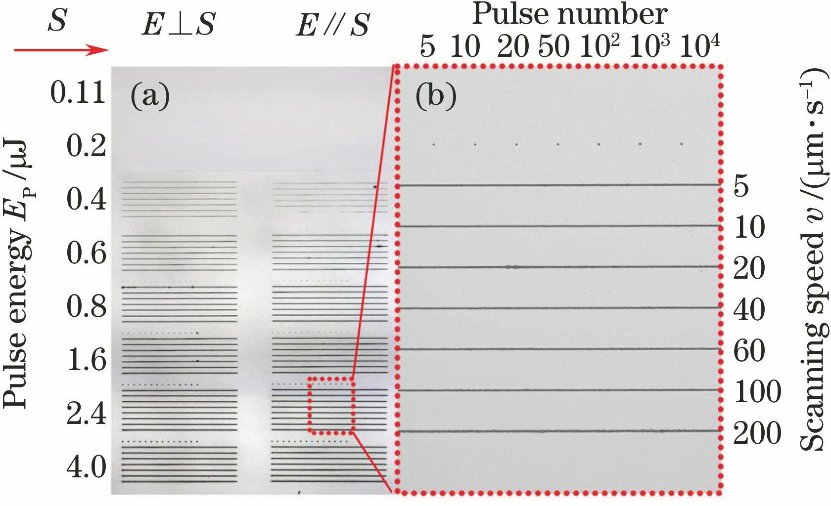
图 2. 不同参数时CaF2晶体表面烧蚀孔的SEM图。(a) A=0.4 μJ,N=10;(b) A=0.6 μJ,N=20;(c) A=4 μJ,N=100;(d) A=4 μJ,N=1000
Fig. 2. SEM images of ablation holes on CaF2 crystal surface with different parameters. (a) A=0.4 μJ, N=10; (b) A=0.6 μJ, N=20; (c) A=4 μJ, N=100; (d) A=4 μJ, N=1000

图 3. 静止聚焦情况下CaF2晶体的激光诱导烧蚀的参数变化情况。(a)烧蚀孔直径平方D2与激光能量的变化关系;(b)能流密度阈值与激光脉冲数量的变化关系;(c)烧蚀孔直径与表面能流密度的变化关系
Fig. 3. Parameters of CaF2 crystal in stationary focusing case. (a) Squared diameter D2 of the ablation holes versus the pulse energy Ep; (b) energy flux density threshold versus laser pulse number; (c) energy flux density versus the diameters of ablation holes

图 4. CaF2晶体表面部分烧蚀线的SEM图。(a)(d) A=0.8 μJ,v=60 μm/s;(b)(e) A=1.6 μJ,v=5 μm/s;(c)(f) A=2.4 μJ,v=5 μm/s
Fig. 4. SEM images of ablation lines on CaF2 crystal surface with different parameters. (a)(d) A=0.8 μJ, v=60 μm/s; (b)(e) A=1.6 μJ, v=5 μm/s; (c)(f) A=2.4 μJ, v=5 μm/s

图 5. 烧蚀线宽度与激光扫描速度的变化关系。(a) E⊥S;(b) E//S
Fig. 5. Widths of ablation lines as a function of scanning speed. (a) E⊥S; (b) E//S


表 1静止聚焦和动态扫描两种情况下的加工参数
Table1. Processing parameters for stationary focusing case and dynamic scanning case
|
表 2不同脉冲数量下激光烧蚀孔的有效半径、烧蚀能量阈值和烧蚀能流密度阈值
Table2. Calculated results of effective radius, threshold of energy and energy flux density of ablation holes on the crystal surface obtained under different pulse numbers
|
郭太勇, 张立木, 任莹莹, 蔡阳健, CarolinaRomero, JavierR.VazquezdeAldana. 飞秒激光烧蚀氟化钙晶体表面特性[J]. 光学学报, 2019, 39(1): 0126019. Taiyong Guo, Limu Zhang, Yingying Ren, Yangjian Cai, Romero Carolina, R. Vazquez de Aldana Javier. Surface Characteristics of CaF2 Crystal Ablated by Femtosecond Laser[J]. Acta Optica Sinica, 2019, 39(1): 0126019.


 PDF全文
PDF全文

