光学学报, 2021, 41 (1): 0124001, 网络出版: 2021-02-23
人工表面等离激元超材料  下载: 3341次特邀综述
Spoof Plasmonic Metamaterials
图 & 表
图 1. 三维SSPP结构。(a) SSPP双向弯曲分波器,其用馈线(feeding wire)和探针(detecting probe)激励[11];(b)周期性分叉缝结构[12];(c)周期性分叉缝结构的等效电路拓扑[12];(d)计算及仿真得到的周期性分叉缝结构的色散曲线[12]
Fig. 1. 3D SSPP structures. (a) SSPP bidirectional bending splitter with feeding wire and detecting probe as excitation[11]; (b) periodic bifurcated slit-decorated structure[12]; (c) equivalent circuit topology of periodic bifurcated slit-decorated structure[12]; (d) calculated and simulated dispersion curves of periodic bifurcated slit-decorated structure
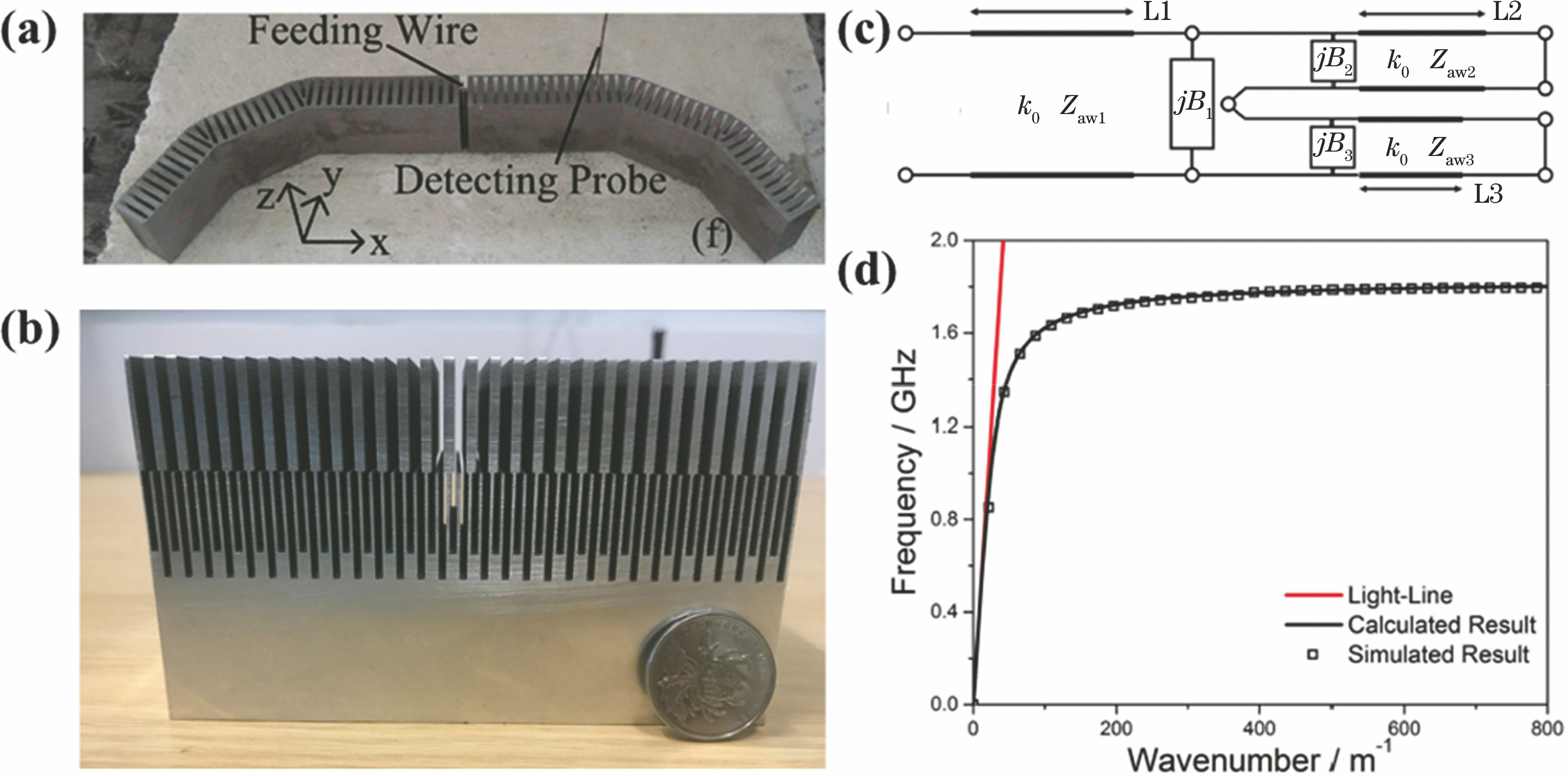
图 2. 柔性超薄SSPP传输线及其传输特性[10] 。(a)柔性传输线实物图;(b)弯折传输线仿真结构;(c)近场仿真结果;(d)弯折传输线实物图;(e)近场测试结果
Fig. 2. Ultrathin and flexible SSPP transmission line and its propagation properties[10]. (a) Photograph of flexible transmission line; (b) simulated structure of curved transmission line; (c) simulated near-field result; (d) photograph of curved transmission line; (e) measured near-field result

图 3. SSPP传输线抑制信道间互耦[16] 。(a)传输线结构;(b)传输系数和耦合系数的实验结果
Fig. 3. Crosstalk suppression using SSPP transmission lines[16]. (a) Structure of transmission lines; (b) experimental results of transmission and coupling coefficients

图 4. SSPP传输线的低损耗性能研究[17] 。(a)传输线结构;(b)相同尺寸微带线;(c)散射参数的实验结果对比
Fig. 4. Low-loss properties of SSPP transmission line[17]. (a) Structure of transmission line; (b) micro-strip line with same size; (c) comparison of measured scattering parameters

图 5. SSPP的高效激励结构。(a)共面波导与SSPP传输线的高效转换[33];(b)微带线与SSPP传输线的高效转换[34];(c)共面波导与SSPP传输线间的转换结构的散射参数的仿真与实验结果[33];(d)微带线与SSPP传输线间的转换结构的散射参数的仿真与实验结果[34]
Fig. 5. High-efficiency excitation structure of SSPP. (a) High-efficiency conversion between coplanar waveguide and SSPP transmission line [33]; (b) high-efficiency conversion between micro-strip and SSPP transmission line [34]; (c) simulated and measured S parameters of conversion structure between coplanar waveguide and SSPP transmission line [33]; (d) s

图 6. 基于SSPP的超宽带3 dB功分器[40] 。(a)结构示意图;(b)传输系数和反射系数的实验结果
Fig. 6. SSPP-based ultra-broadband 3 dB power divider[40]. (a) Structure diagram; (b) measured transmission and reflection coefficients

图 7. 基于SSPP的分频器和3 dB定向耦合器[42] 。(a)分频器结构示意图;(b)分频器的仿真和实验结果;(c) 3 dB定向耦合器的结构示意图;(d) 3 dB定向耦合器的仿真和实验结果
Fig. 7. SSPP-based frequency splitter and 3 dB directional coupler[42]. (a) Structural diagram of frequency splitter;(b) simulated and measured results of frequency splitter; (c) structural diagram of 3 dB directional coupler; (d) simulated and measured results of 3 dB directional coupler

图 8. 基于SSPP的分频器[43] 。(a)分频器的结构示意图;(b) 5.2 GHz电场分布的仿真结果;(c) 10.2 GHz电场分布的仿真结果;(d) 5.2 GHz电场分布的实验结果;(e) 10.2 GHz电场分布的实验结果
Fig. 8. SSPP-based frequency splitter[43]. (a) Structural diagram of frequency splitter; (b) simulated electric field distribution at 5.2 GHz; (c) simulated electric field distribution at 10.2 GHz; (d) measured electric field distribution at 5.2 GHz; (e) measured electric field distribution at 10.2 GHz

图 9. 基于SSPP的环形谐振器[44] 。(a)谐振器的结构示意图;(b) 0.98 THz时电场分布的仿真结果
Fig. 9. SSPP-based ring resonator[44]. (a) Structural diagram of resonator; (b) simulated electric field distribution at 0.98 THz

图 10. SSPP滤波器。(a)SSPP耦合式滤波器[45];(b)由反对称SSPP传输线和基片集成波导组成的混合带通滤波器[46];(c)紧凑型混合带通滤波器[47]
Fig. 10. SSPP-based filters. (a) SSPP-coupled filter [45]; (b) hybrid band-pass filter composed of anti-symmetric SSPP transmission line and substrate-integrated waveguide [46]; (c) compact hybrid band-pass filter [47]

图 11. SSPP天线。(a)由梯度单元组成的相位可调的SSPP天线[51];(b)基于SSPP的天线阵列及其馈电网络[52];(c)奇模SSPP天线[53];(d)基于SSPP的小型化天线[54]
Fig. 11. SSPP antennas. (a) Phase-tunable SSPP antenna composed of gradient units [51]; (b) SSPP-based antenna array and its feeding network [52];(c) odd-mode SSPP antenna [53];(d) miniaturized SSPP-based antenna [54]

图 12. 三维SSPP结构[55]。(a)周期开槽金属圆柱示意图;(b)等效人工电磁媒质圆柱体示意图
Fig. 12. 3D SSPP structure[55]. (a) Diagram of periodic corrugated metallic cylinder; (b) diagram of cylinder with equivalent artificial electromagnetic medium

图 13. 超薄SLSP结构及其物理特性[56] 。(a)测量近场谐振的实验装置;(b)用不同介质覆盖的超薄开槽金属盘的近场响应谱;(c)近场响应的仿真结果和模式;(d)近场响应的实验结果和模式
Fig. 13. Ultrathin SLSP structure and its physical properties[56]. (a) Experimental setup for measuring near-field resonance; (b) near-field response spectra of ultrathin corrugated metallic disk covered by different dielectric pads; (c) simulated near-field responses and patterns; (d) measured near-field responses and patterns

图 14. 超薄开槽金属盘的物理特性[57] 。(a)周期开槽金属盘散射截面积的仿真结果与计算结果;(b)各阶谐振电场分布的仿真结果
Fig. 14. Physical properties of ultrathin corrugated metallic disk[57]. (a) Simulated and calculated scattering cross sections of periodic corrugated metallic disk; (b) simulated electric field distribution corresponding to each order resonance

图 15. 亚波长螺旋形开槽金属圆盘谐振谱[59] 。(a)近场频谱的实验结果和散射截面频谱的计算结果;(b) LSP电偶极子谐振的电场分布;(c) LSP磁偶极子谐振的电场分布
Fig. 15. Resonance spectra of sub-wavelength spiral corrugated metallic disk[59]. (a) Experimental near-field spectrum and calculated ECS spectrum; (b) electric field distribution of electric LSP resonance; (c) electric field distribution of magnetic LSP resonance

图 16. 螺旋形开槽金属圆盘谐振谱的仿真与实验结果以及各谐振点处相应的近场分布实验结果[61]
Fig. 16. Measured and simulated resonance spectra of spiral corrugated metallic disk and measured near-field distribution corresponding to each resonance point [61]

图 17. SLSP的模式杂化[62] 。(a)间距很近的两个螺旋形开槽圆盘结构;(b)间隔中心的电场增强;(c)模式的谐振频率和场增强的最大值与间距大小的函数关系
Fig. 17. Mode hybridization of SLSP[62]. (a) Two closely spaced spiral corrugated metallic disks; (b) electric field enhancement at gap center; (c) mode resonance frequency and maximum field enhancement versus gap size

图 18. SSPP放大器[37] 。(a)反对称式SSPP传输线;(b)放大器的整体结构;(c)传输系数的仿真与实验结果;(d)~(g) 14,16,18,20 GHz处电场分布的测试结果
Fig. 18. SSPP amplifier[37]. (a) Anti-symmetric SSPP transmission line; (b) overall structure of amplifier; (c) simulated and measured transmission coefficients; (d)--(g) measured electric field distributions at 14, 16, 18, 20 GHz

图 19. SSPP倍频器[63] 。(a)结构图;(b)频谱实测结果;(c)输入为8 GHz基频时的实测电场分布;(d)输出为16 GHz二次谐波时的实测电场分布;(e)输入为10 GHz基频时的实测电场分布;(f)输出为20 GHz二次谐波时的实测电场分布
Fig. 19. SSPP frequency-doubling generator [63]. (a) Structural diagram; (b) measured spectrum; (c) measured electric field distribution when incident fundamental frequency is 8 GHz; (d) measured electric field distribution when output second harmonic frequency is 16 GHz; (e) measured electric field distribution when incident fundamental frequency is 10 GHz; (f) measured electric field distribution when output second harmonic frequency is 20 GHz

图 20. 基于变容管的SSPPs的倍频控制[64] 。(a)前向二次谐波的产生;(b)后向二次谐波的产生;(c)非线性SSPP的单元结构
Fig. 20. Frequency doubling regulation of SSPPs based on varactor diodes [64]. (a) Forward second-harmonic generation; (b) backward second-harmonic generation; (c) unit structure of nonlinear SSPPs

图 21. SSPP可调滤波器[65]。(a)整体结构图;(b)单元结构图
Fig. 21. SSPP-based tunable filter [65]. (a) Overall structure; (b) unit structure


图 23. 电控SLSP结构[67] 。(a)反射系数的仿真结果;(b)反射系数的实验结果;(c)传输系数的仿真结果;(d)传输系数的实验结果;(e)电场分布的仿真结果;(f)电场分布的实验结果
Fig. 23. Electronically tunable SLSP structures[67]. (a) Simulated reflection coefficients; (b) measured reflection coefficients; (c) simulated transmission coefficients; (d) measured transmission coefficients; (e) simulated electric field distributions; (f) measured electric field distributions

图 24. 基于SSPP技术的亚波长间距双通道信号无线通信射频收发系统[68]
Fig. 24. Radio frequency transceiver for SSPP-based wireless communication system with sub-wavelength-spacing dual-channel signals[68]

图 25. 基于SSPP的亚波长间距双通道信号无线通信系统及测试结果[68]。(a)测试环境示意图;(b)接收机所在环境;(c)发射机所在环境;(d)传输前的电影信号;(e)经SSPP无线通信系统传输后的电影信号;(f)经传统无线通信系统传输后的电影信号
Fig. 25. SSPP-based wireless communication with sub-wavelength-spacing dual-channel signals and measured results [68]. (a) Schematic of test scenario; (b) test scenario of receiver; (c) test scenario of transmitter; (d) movie signals before transmission; (e) movie signals after transmission through SSPP-based wireless communication system; (f) movie signals after transmission through traditional wireless communication system

图 26. 数字式SSPP超材料结构[69]。(a)结构示意图;(b)调控单元示意图;(c)色散曲线
Fig. 26. Digital SSPP metamaterial structure [69]. (a) Structural diagram; (b) diagram of control unit; (c) dispersion curves

图 27. 加载有变容管的多比特数字化SSPP系统[28]。(a)单元等效电路模型;(b)(c)引入变容管建立可编程SSPPs;(d)单元几何构型;(e)实物俯视图;(f)(g)实物仰视图
Fig. 27. Multi-bit digital SSPP system loaded by varactor diodes [28]. (a) Equivalent circuit model of unit; (b)(c) programmable SSPPs constructed by loading varactor diodes; (d) geometric structure of unit; (e) top view of physical map; (f)(g) bottom view of physical map

张浩驰, 何沛航, 牛凌云, 张乐鹏, 崔铁军. 人工表面等离激元超材料[J]. 光学学报, 2021, 41(1): 0124001. Haochi Zhang, Peihang He, Lingyun Niu, Lepeng Zhang, Tiejun Cui. Spoof Plasmonic Metamaterials[J]. Acta Optica Sinica, 2021, 41(1): 0124001.


 PDF全文
PDF全文

