Photonics Research, 2020, 8 (7): 07001124, Published Online: Jun. 4, 2020
Distance-controllable and direction-steerable opto-conveyor for targeting delivery  Download: 717次
Figures & Tables
Fig. 1. Schematic diagrams of (a) the experimental setup and the opto-conveyor. R1, reflection mirror 1; L1, L2, L3, and L4, lenses. S L S T F L F T α y ′ F S F G L F G T F S y ′ F S z ′ y ′ z ′ F S T F S L F S y ′
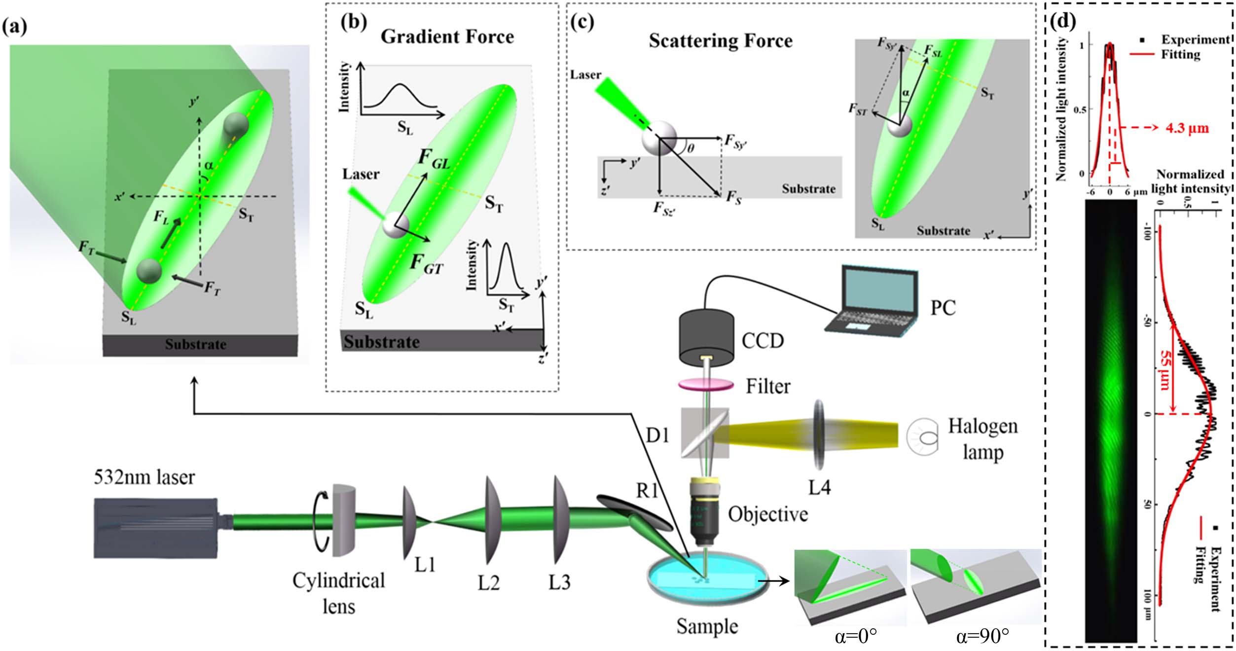
Fig. 2. (a) Formation of the opto-conveyor on the substrate. The distributions of the electric intensity in (b) x o y x o z y o z r = 3.5 μm x y z S x S y S z x y z

Fig. 3. Confining forces (F T F L S T S L

Fig. 4. (a) Targeting delivery processes and (b) the delivery trajectories of the PS microparticles at six different start points. The yellow dotted lines show the trajectories of microparticle movement. The green ellipses denote the opto-conveyor, and the reddish dots denote the positions of the microparticles every second.

Fig. 5. Delivery processes of the microspheres for five different optical powers of 221.7 mW, 337.6 mW, 484.1 mW, 702.5 mW, and 769.4 mW, respectively. The incident angle θ α

Fig. 6. Speed distributions during microparticle delivery processes as functions of (a) time and (b) position for five different optical powers of 221.7 mW, 337.6 mW, 484.1 mW, 702.5 mW, and 769.4 mW in the experiments, respectively. (c) The theoretical and experimental distributions of the transport speed and driving force at the optical power of 337.6 mW. (d) The experimental and theoretical maximum speed and the delivery time consumption versus the optical power, respectively.

Fig. 7. (a) Relationship between the irradiation time, optical power, and the delivery distance, and (b) relationship between the irradiation time and the delivery distance at the optical power of 484.1 mW. The dotted lines show the delivery distance at the irradiation times of 4 s, 5 s, 6 s, and 22 s, respectively.

Fig. 8. Delivery distances of microparticles at the optical power of 484.1 mW with the delivery periods of 4 s, 5 s, 6 s, and 26 s, respectively. The incident angle θ α

Fig. 9. (a) Delivery trajectories for different azimuthal angles at the optical power of 484.1 mW and the incident angle of 45°. The optical images of the opto-conveyors are shown in each inset. (b) The experimental and theoretical delivery distances, and (c) the experimental and theoretical maximum speeds of the microparticles versus azimuthal angles.

Fig. 10. Simultaneous delivery of microparticles to a targeting object at the optical power of 484.1 mW, the incident angle of 30°, and the azimuthal angle of 0°. The dotted lines denote the opto-conveyor.


Table1. Theoretical and Experimental Results on the Control of the Delivery Distance
| ||||||||||||||||||||||||
Zhen Che, Wenguo Zhu, Yaoming Huang, Yu Zhang, Linqing Zhuo, Pengpeng Fan, Zhibin Li, Huadan Zheng, Wenjin Long, Wentao Qiu, Yunhan Luo, Jun Zhang, Jinghua Ge, Jianhui Yu, Zhe Chen. Distance-controllable and direction-steerable opto-conveyor for targeting delivery[J]. Photonics Research, 2020, 8(7): 07001124.


 PDF全文
PDF全文

