Chinese Optics Letters, 2018, 16 (11): 110601, Published Online: Nov. 11, 2018   

In-fiber integrated optics: an emerging photonics integration technology [Invited] Download: 930次

Author Affiliations
1 Key Laboratory of In-Fiber Integrated Optics, Ministry of Education, College of Science, Harbin Engineering University, Harbin 150001, China
2 Photonics Research Center, School of Electric Engineering and Automation, Guilin University of Electronics Technology, Guilin 541004, China
Abstract
In-fiber integrated optics is an attempt to use silica fiber as a substrate, integrating various optical paths or optical components into a single fiber, to build a functional optical device or component, and to realize a micro optical system, achieving various functions. In-fiber integrated optics is expected to be a new branch of photonics integration. This integration technique enables convenient light beams control and manipulation inside in one fiber. It also provides a research platform with micro and nano scale for interaction between light wave and microfluidic materials. In this review, we briefly summarize the main ideas and key technologies of the in-fiber integrated optics by series integration examples.

1. INTRODUCTION

Integrated technology plays an increasingly important role in the field of micro and nano optics and photonics. Integrated optics began with the concept proposed by Dr. Miller of Bell Laboratory in 1969[1]. It presents a prototype for integrated optics with dielectric materials as a substrate. In 1972, Somekh and Yariv proposed the idea of integrating optical devices and electronic devices simultaneously on the same semiconductor substrate[2]. Since then, researchers have made use of various materials and different fabrication methods to make integrated optical devices and photoelectric hybrid integrated devices.

Based on the concept of integrated optics, the fiber Bragg grating was proposed by Hill et al. in 1978, who first wrote the reflector or filter into the optical fiber[3]. It has pioneered the integration of optical passive devices into optical fibers. The Fabry–Perot (F–P) interferometer integrated in fiber was developed with the help of a fiber Bragg grating. On the other hand, in order to improve the optical communication channel density, the concept of a multicore optical fiber with multiple optical information channels in the same fiber was proposed in 1979[4]. Multicore optical fiber technology has encountered two main problems and difficulties in the application of early optical communication. One is the difficulty of the multicore optical fiber connection, and the other is the cross talk between each fiber core of multicore fiber in long distance communication. With the development and maturation of wavelength division multiplexing (WDM) and dense WDM (DWDM) technology, the scheme of multicore optical fiber solutions for dense channel communication has lost its advantages at that age. However, there are still some work reports on the application of multicore fiber, for instance, Kishi et al. carried out the theoretical research of multicore coupling[5]. To realize the parallel output of a multi-laser in a single optical fiber, Cheo et al. carried out the research of a multicore fiber array laser[6]. In recent years, with the need for channel capacity expansion, the multicore fiber optic technology in the space division multiplexed in one fiber has been re-mentioned. Multicore optical fiber intercore isolation technology[7,8] and multicore optical fiber fan in/out connection technology[9,10] are also developed. The development of new optical fiber manufacturing technology has injected new vitality into multicore optical fiber communication.

Different from long distance optical fiber communication, in most cases, in-fiber integrated optics focuses on the interaction between the short-distance waveguide itself and its surrounding waveguides. At the same time, special attention is paid to the interaction between the optical fiber internal waveguide and the material outside the fiber. These interactions are often caused by the interaction between the optical fiber end or the evanescent light field of the fiber and surrounding matter. In some special cases, in-fiber integration optics is also concerned with the long-range transmission characteristics and their interactions with the surrounding environment. Such as, the application of multicore optical fiber-based space division multiplexing optical communication, or remote dual optical path distributed interferometry. In-fiber integrated optics is committed to achieving such a goal and is devoted to the following basic research: (1) design and manufacture new functional fiber; (2) develop integration technology of functional optical devices or components; and (3) further develop the multiple functional microsystem integration technology and method of in-fiber integrated optics. The aim is to complete and implement the tasks of light wave control, light wave signal exchange, information processing in optical fiber, and information extraction from the interaction between fiber and the surrounding environment.

2. FUNCTIONAL FIBERS FOR IN-FIBER INTEGRATED OPTICS INFRASTRUCTURE

We know that special microstructure waveguide core fiber is the basic substrate material for fiber integrated optics. It is the key to constructing fiber integrated optical devices and it is also the premise for realizing fiber integrated micro-optical systems. Based on the actual demand, the microstructure waveguide core of the optical fiber is investigated and reconstructed. For example, the twin-core polarization-maintaining optical fiber is needed for the development of integrated interferometers; the refractive index of each core slightly different from multicore optical fiber is required for integrated parallel multifiber Bragg grating; and multicore rare earth-doped optical fiber could be used to build multiwavelength integrated fiber lasers in parallel. Functional fibers could provide basic material assurance for the research of in-fiber integrated optics.

2.2 A. Optical Path Separation Multicore Fiber

Multicore optical fiber (MCF) is a typical refractive index guiding microstructured optical fiber. Multiple fiber cores in single fiber make it possible to construct more complex optical paths in a single fiber. Compared with single core single-mode fiber (SMF), it consists of multiple independent fiber cores (at least two cores) in one public cladding. Each core in the optical fiber is an independent light wave channel; therefore, multicore fiber is considered as a multilight-wave channel or multi-optical-path integrated optical fiber. Figures 1(a) and 1(b) show the cross-sectional photos of several typical multicore fibers. For instance, twin-core fiber can be developed as a Michelson interferometer or Mach–Zehnder interferometer (MZI) for sensing, such as refractive index, temperature, and strain[11,12]. The seven-core fiber can be used as a multicore fiber connector with ultralow cross talk and low insertion losses[13]. Another kind of optical path separation multicore fiber is called multi-polarization-maintaining-core fiber. The fibers’ multicores have an elliptical shape and are embedded in the inner wall of the silica capillary tube, as shown in Fig. 1(c). Some application examples of these multicore fibers are given herein later in this review.

Fig. 1. Optical path separated multi-core fibers. (a) Twin-core and three-core fibers. (b) Four-core and seven-core fibers. (c) Central holey multi-elliptic-core fibers.

下载图片 查看所有图片

2.3 B. Multicore Optical Fiber for Light Beam Control

In a discrete optical system, waveguide arrays can be used to control the optical wavefronts with desired diffraction properties[14]. If multiple cores are arranged in a well-designed array, the control of the light field can be realized through the mutual coupling between the waveguides. Through the coupling between adjacent cores, the input light can broaden the spatial distribution[1517" target="_self" style="display: inline;">–17], just as diffraction in continuous media. For that, we designed and fabricated several kinds of specially designed multicore arranged fibers, such as multicore distributed in a linear array, multicore distributed in an annular array, and multiring waveguides around the central hole, as shown in Fig. 2.

Fig. 2. Phase array controlled multi-core fibers.

下载图片 查看所有图片

2.4 C. Optical Paths and Microfluidic Materials Channel Hybrid Integrated Fiber

If microfluidic channels and optical waveguides can be integrated into a single optical fiber, they will have great potential in optofluidic devices. They can realize convenient optical coupling and obviously increase the integration level of the devices. Microstructured optical fibers with microholes in the micrometer scale diameters can contain gas or liquid with the volume of a microliter or a nanoliter. Therefore, they are desired carriers for trace detection. This one-dimensional holey structure provides a long cell for the contact between samples and the waveguide, which breaks through the limitations of the traditional optical fiber and exhibits irreplaceable advantages in the fields of analyses. Here, a series of specially designed optical fiber is given in Fig. 3, such as suspended-core fiber [see Fig. 3(a)], capillary fiber with a ring core [as shown in Fig. 3(b)], and two kinds of twin-core fiber with a microhole as the microfluidic channel [see Figs. 3(c) and 3(d)]. The suspended core fiber has a core suspend on the inner wall of the capillary, as shown in Fig. 3(a); for building an interferometer, the second core is added which is embedded in the middle of the capillary wall. Another scheme is shown in Fig. 3(d): twin-core fiber with an eccentric microhole close to the central core for interaction between the light beam and microfluidic materials, while the reference beam propagates along the core away from the central core. These fibers could be used to build in-fiber integrated optofluidic devices for refractive index detection, chemiluminescence, and fluorescence detection as well as electrophoresis separation and detection.

Fig. 3. Optical paths and microfluidic materials channel hybrid integrated fiber.

下载图片 查看所有图片

2.5 D. Photonic Crystal Fibers

The photonic crystal fiber (PCF), owing to the arrayed microhole structure, makes it suitable for biochemistry sensing, strain and temperature measurement, and numerous optical integrated devices. The PCF with a solid core can be filled with liquid or polymers into the surrounding holes for evanescent-wave sensing of chemicals or biomolecules, as in Figs. 4(a) and 4(b). The interaction of light with filled matter in the holes of the cladding can be explored for measuring the concentration of gas or detecting biomolecules[18,19]. While the photonic bandgap fiber is another kind of PCF with an airhole taking place of the solid core in the center. Due to the photonic bandgap effect, the light is confined in the air core. When the holes are filled with other materials, the optical channel can also be the interacting substance channel for modulating the optical field, as in Figs. 4(c) and 4(d). By injecting different materials into the hole, the transverse mode would change due to the refractive index difference between the core and the cladding[20,21]. These features make the PCF convenient for incorporating with optoelectrical devices, biochemical sensors, and even molecule detectors.

Fig. 4. Photonic crystal fibers.

下载图片 查看所有图片

Fig. 5. In-fiber integrated optical components based on several fabrication techniques. (a) Fused splicing and tapering of fiber components. (b) Optical fiber end components by polishing. (c) Fused sphere, holey fiber bubble by CO2 laser and groove by 157 nm laser.

下载图片 查看所有图片

3. FUNDAMENTAL OPTICAL DEVICE CONSTRUCTION AND FABRICATION

Based on the fibers mentioned above, many micro processing technologies, including fused splicing technology for in-fiber coupler/splitter, the side polishing technique, fiber end machining, melting and tapering, chemical etching and coating, and laser micro mashing technology[22], were introduced to fabricate several in-fiber integrated optical devices and components[15,2328" target="_self" style="display: inline;">28], as shown in Fig. 5.

3.2 A. In-fiber Integrated Coupler

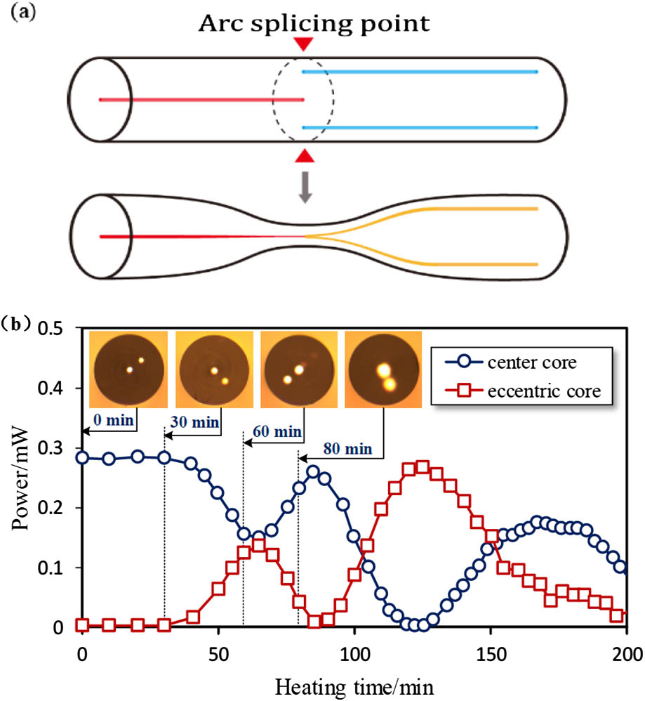
There are two ways to build an in-fiber integrated coupler for multicore fibers. One is to realize the coupling of the light wave by fused splicing of the SMF with the multicore fiber, and then heating and stretching at the splicing joint to make a bi-tapered fiber zone, thus light waves could be coupled into each core of the multicore fiber from the SMF[24,29], as shown in Fig. 6(a). The other is through thermal diffusion technology, which allows each core to expand through thermal diffusion to achieve coupling between light waves in each core[30,31] [see Fig. 6(b)].

Fig. 6. In-fiber integrated coupler technologies.

下载图片 查看所有图片

3.3 B. Multicore Fiber Fan-out Device

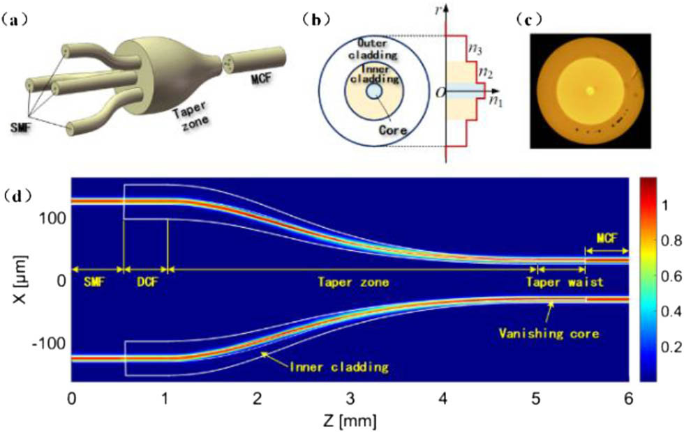
In transmission systems, one of the key components used to realize space division multiplexing (SDM) and expand the transmission capacity is the multicore fiber fan-out component as a connecting device between the multicore fiber and SMF[13]. A “vanishing core” technology[32] can be used to fabricate the multicore fiber fan-out component. A four-core fiber fan-out device, as an example, is fabricated by four double cladding fibers embedded in a fiber substrate, as shown in Fig. 7(a). The double cladding fiber has a center core, an inner cladding, and an outer cladding, with refractive indices of n1, n2, and n3, respectively, as shown in Figs. 7(b) and 7(c). The four-core fiber fan-out device, as a multicore fiber coupler, is typically spliced to standard SMF in its wide end and connected with a multicore fiber in its narrow end, as shown in Fig. 7(a). The center core (n1) can support a single propagating mode in the wide end. However, in the narrow end the center core is vanishing and the outer cladding (n2) serves as a fiber core to ensure efficient optical mode field transformation between the narrow end and the connected multicore fiber. The beam propagation method (BPM) simulation results depict the mode field propagation and the vanishing core process in the fiber coupler device, as shown in Fig. 7(d). This kind of components can not only be used to link multicore fiber separated to each SMF, but also could be used for mode field shaping and NA and mode polarization adiabatic transformation by the gradually tapered optical waveguide.

Fig. 7. Configuration of multi-core fiber fan-out component.

下载图片 查看所有图片

3.4 C. Multicore Fiber Bragg Grating

Multicore fiber can be used to write Bragg gratings in parallel. Due to the multiple parallel fiber grating can not only be used to measure the tensile strain, but also can be used to measure the differential strain. Therefore, this kind of fiber Bragg grating integration device is useful for configuring a fiber optic bending sensor for curvature measurement[33]. In the writing process of multicore fiber Bragg gratings, because the fiber core deviates from the axisymmetric center, the fiber itself as a cylindrical lens has a certain effect on the quality of Bragg gratings writing. Fig. 8(a) shows several typical cases when the incident beam (be used to write Bragg grating) and the fiber core orientation angle are different, and the reflection spectrum of the eccentric fiber Bragg grating produces a certain deviation[34]. Figure 8(b) shows that the reflection spectra of the Bragg grating written in each fiber core are different; even the three Bragg gratings are written by a same phase mask.
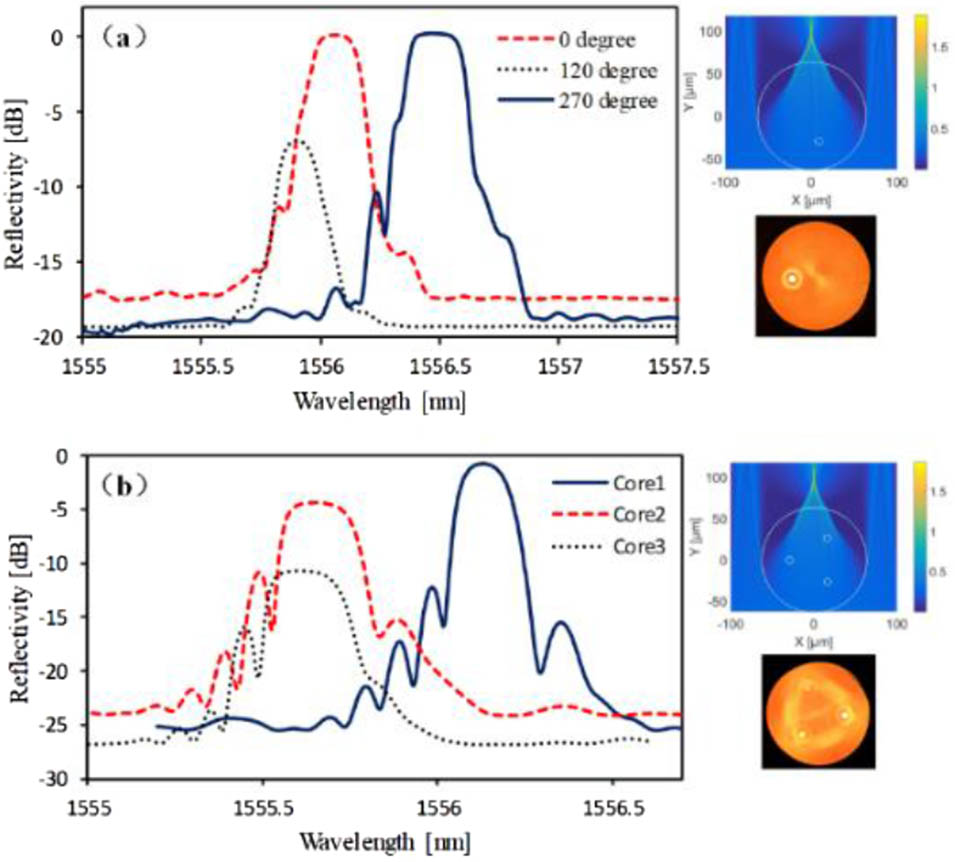
Fig. 8. Eccentric core fiber and three-core fiber Bragg gratings written by a phase mask.

下载图片 查看所有图片

3.5 D. In-fiber Integrated Modulator

Poled fiber can be constructed as an in-fiber integrated modulator for communication applications, especially an intrinsic phase-modulating device, including electro-optic intensity modulators, and Mach–Zehnder or other types of interferometers[35].

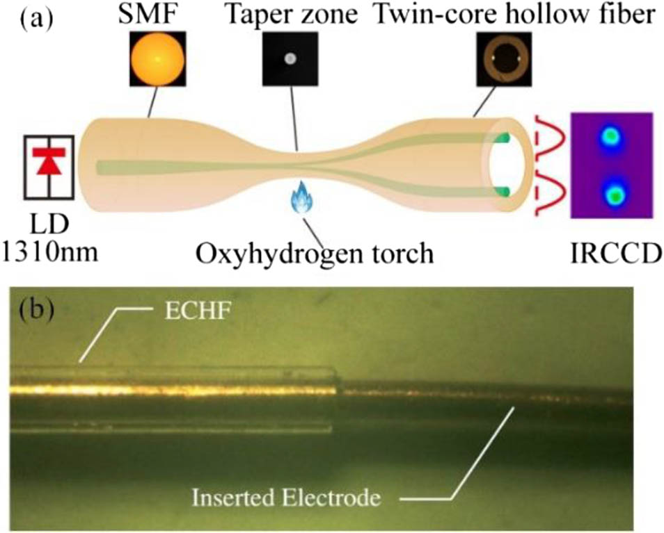
By using the special designed hollow twin-core fiber, in which the cores have an elliptical shape and are embedded in the inner wall of the silica capillary tube, as shown in Fig. 1(c), an in-fiber integrated modulator was configured and demonstrated[27]. Figure 9(a) shows that the main process first builds a Michelson interferometer through fused splicing of an SMF and a twin-core hollow fiber, then inserts a poling anode tungsten wire into the hollow of the fiber, and deposits a thick gold cathode film on the cladding surface. Finally, a fiber electro-optic modulator is fabricated, as shown in Fig. 9(b). The experiment results show that the device has excellent intensity modulation ability in the frequency range from 149 to 1000 Hz. The half-wave voltage and the effective second-order nonlinear coefficient would be 135 V and 1.23 pm/V, respectively.

Fig. 9. In-fiber integrated electro-optic intensity modulator.

下载图片 查看所有图片

3.6 E. In-fiber Integrated Multi-lasers

As the multicore fiber can carry or transmit information in each core separately, the fiber amplifications or the fiber lasers can also be integrated into multicore fiber to form a multi-laser, which can substantially lower the cost and reduce the size, such as seven-core fiber distributed feedback (DFB) lasers[36]. In the implementation process, multicore fiber π-phase shift gratings are fabricated to generate efficient unidirectional laser. Figure 10(a) represents the lateral UV writing beams and the number of each core that are convenient to describe. By the cylindrical structure of the fiber, the UV beams can be expected to expose all cores for inscribing all fiber gratings at once, as Fig. 10(b) illustrates. The transmission spectrum of each core shown in Fig. 10(c) indicates that the largest spectral widths are in cores 2 and 3 due to the lensing effect caused by the front surface of the fiber. The spectra of cores 0,1,4, and 5 show two resonances, which are ascribed to polarization splitting. The experimental setup characterizing each core laser output is displayed in Fig. 10(d). A bundle of seven fibers is tapering and splicing to a section of the multicore Er-doped fiber (MC-EDF), which contains MC-DFB gratings.
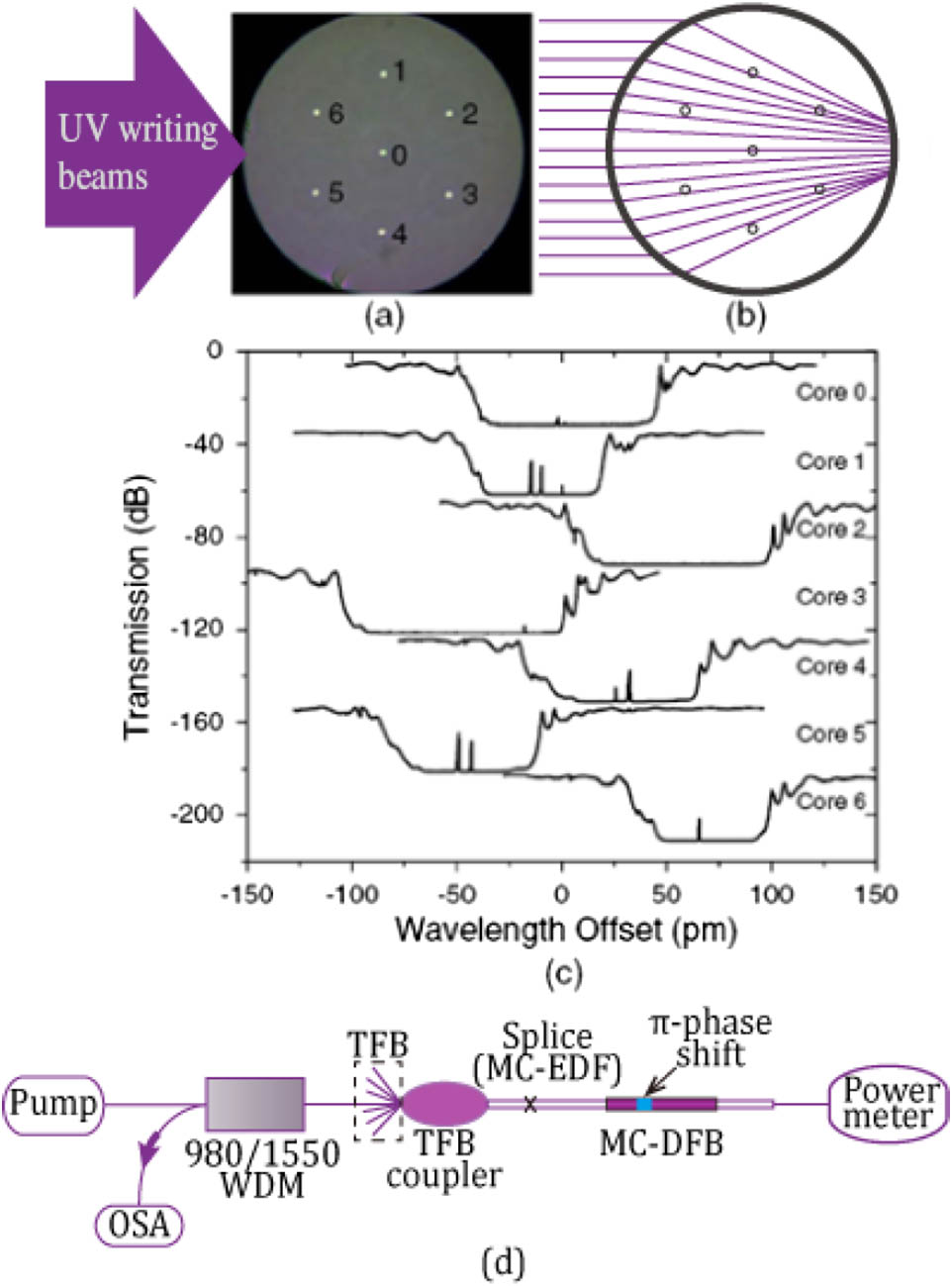
Fig. 10. Seven-core fiber multi-laser and experimental setup. (a) Lateral UV beams on seven-core fiber. (b) Ray trajectory of UV writing beam exposing all cores without obstruction. (c) Transmission spectrum of each core measured by a scanned laser. (d) Experimental setup for measuring the MC-DFB.

下载图片 查看所有图片

3.7 F. In-fiber Integrated Photodetector

Integrating optical fiber with optoelectronic materials is meaningful work. The incorporation of semiconductor junctions into microstructured optical fiber can effectively improve the performance of in-fiber devices or all-fiber optical devices, enabling generating, modulating, and detecting light within the fiber itself (Fig. 11).

The high-pressure chemical vapor deposition (HPCVD) technology can implement the fiber-compatible optoelectronic device fabrication[37]. The process of integrating needs chemical precursor mixtures flowing through microholes by high pressure, precursor decomposition, film deposition, and dopant incorporation. By varying the pressure and controlling the concentration of the dopant, different layer thickness can be achieved. The holey structure is facile to construct semiconductor optoelectronic junction inside the hole. As the semiconductor layers are parallel to the fiber core, it is applicable to efficiently and directly couple light from the fiber core into the semiconductor layers. In the transverse direction of the fiber mode interaction and power transfer can couple from the core into the junctions. Thus, the in-fiber integrated optoelectronic device can realize many functions as transistors, light-emitting diodes, and photodetectors.
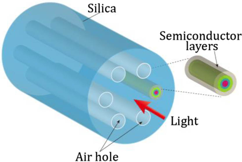
Fig. 11. Optoelectronic photonic crystal fiber with a coaxial semiconductor junction. The junction is composed of several layers of silicon and germanium and is located in a hole adjacent to the fiber core.

下载图片 查看所有图片

4. EXAMPLES OF IN-FIBER INTEGRATED OPTIC SYSTEM

Several functional optical devices are integrated into the same cylindrical optical fiber substrate, which can form a fully functional micro in-fiber integrated optical system. Therefore, it is of great significance to promote the application of in-fiber integrated devices from a single functional unit to multifunctional in-fiber integrated optical microsystems. In order to illustrate the potential applications of in-fiber integrated optics technology, we give some examples, such as a microfluidic device integrated into one fiber constituting a microstructure chemical sensing or microanalysis system; an in-fiber integrated interferometer forms a single fiber-based micro accelerometer; and by using a twin-core fiber and fiber end micro processing technology, an optical fiber-based micro particle manipulation system is also configured.

4.2 A. In-fiber Integrated Optofluidic System

In-fiber integrated optofluidic devices have been used in the fields of chemical and environmental analysis, biosynthesis, and drug delivery due to their specific advantages such as microfluidic control, a large specific surface area, and an integrated light path[3840" target="_self" style="display: inline;">–40]. Yang et al. used a specially designed fiber for the first time to complete fiber-integrated optofluidic detection[39]. Microfluidic control is realized in the optical fiber, and the optical coupling between the optical waveguide and the sample is realized by utilizing the large specific surface area of the optical fiber.

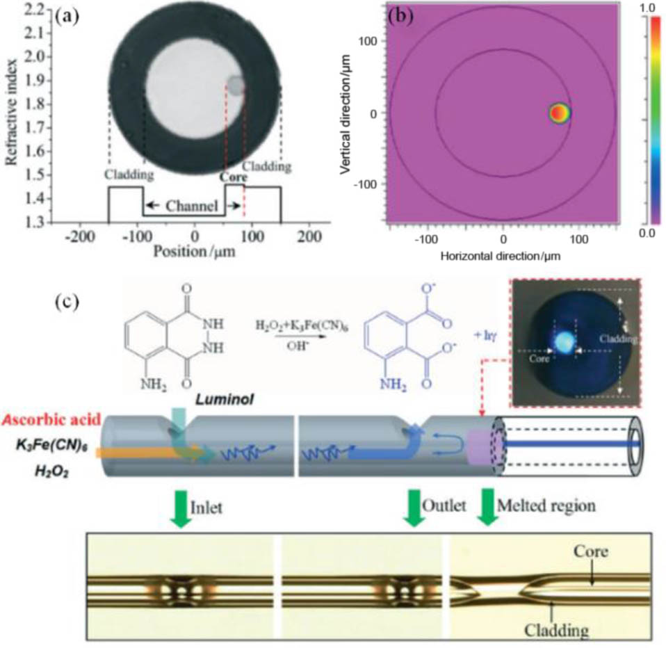
Specifically, they chose hollow suspension core fibers for experiments, as shown in Figs. 12(a) and 12(b). There is a capillary hollow structure in this optical fiber with a suspended optical waveguide on the inner wall of the capillary. The overall experimental device is shown in Fig. 12(c). In order to inject a trace sample into the fiber, the side-wall of the fiber with a suspension core was opened by a carbon dioxide laser. In this way, a tiny reaction area is formed inside the fiber. They used this micro-reaction zone to perform chemiluminescence detection in the fiber. By injecting the sample through the surface of the fiber, stable microflows can be formed within the fiber. They specifically used vitamin C as a reducing agent, hydrogen peroxide as an oxidant, and luminol as a luminescent reagent. Under the catalysis of potassium ferricyanide, luminol participates in the chemiluminescence reaction. Chemiluminescence-generated photons are coupled into the suspended core and detected. The intensity of chemiluminescence correlates with the concentration of vitamin C, and the detection of vitamin C is achieved. The results showed that the linear relationship was detected within a concentration range of 0.1–3.0 mmol/L and the response time is less than 2 s at a total flow rate of 150 μL/min.

Fig. 12. Optofluidic micro system for chemiluminescence reaction monitoring.

下载图片 查看所有图片

4.3 B. In-fiber Integrated Accelerometer

The twin-core fiber can be used to construct a variety of in-fiber integrated devices, such as Michelson interferometer[21] and micro accelerometer[41].

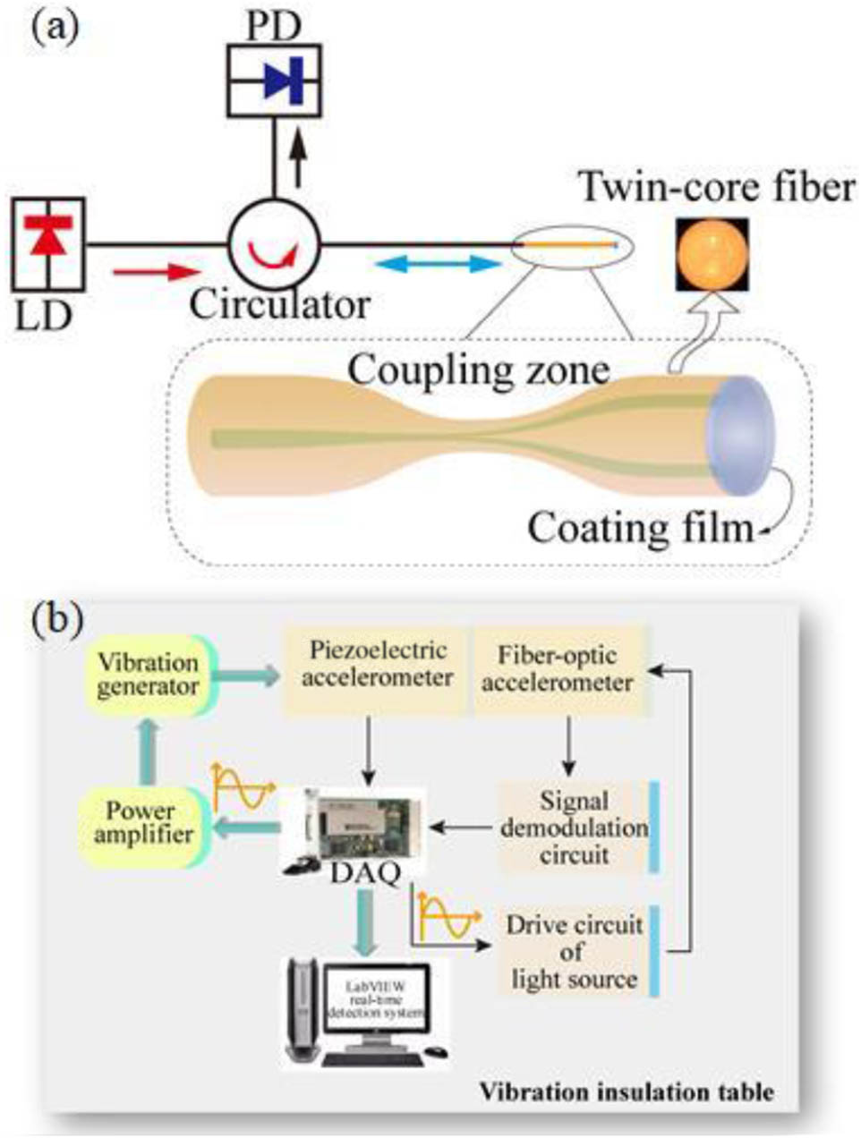
In the micro accelerometer measuring system, the sensing element is based on a twin-core fiber Michelson interferometer, as shown in Fig. 13(a). As a simply supported beam, the twin-core fiber is sensitive to fiber bending caused by acceleration, and the acceleration should be proportional to the force applied to the fiber. Figure 13(b) gives the testing system for measuring the vibration acceleration. The experiment results show that the sensitivity of the accelerometer is 0.09 rad/g at the resonant frequency of 680 Hz. The advantages of such an accelerometer are its small size, flexible construction, and especially excellent ability to compensate the variation of environmental temperature due to the equal optical path changing in the two cores affected by environmental temperature.

Fig. 13. In-fiber integrated accelerometer.

下载图片 查看所有图片

4.4 C. Particle Trapping Micro-optic System

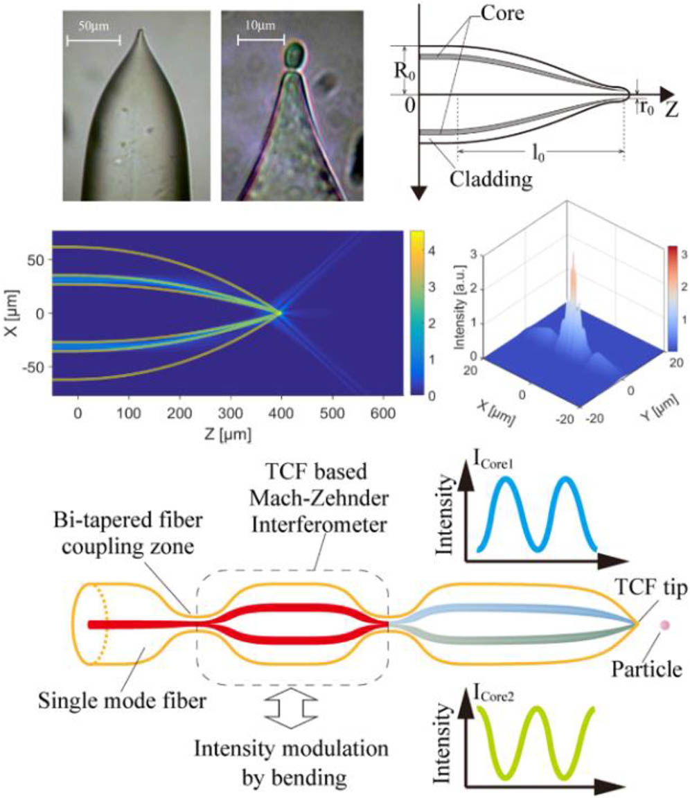
The micro-optic integration system example for particle trapping and manipulating consists of twin-core fiber with an abruptly tapered tip, as shown in Fig. 14. The simulation results based on beam propagation method (BPM) show that a strong focusing phenomenon occurs at the abruptly tapered tip. As a result, a strong enough gradient force well is formed for three-dimensional particle trapping. Specifically, as an optical tweezer device, an in-fiber integrated MZI based on twin-core fiber is introduced to modulate the optical power of the two beam propagation in the two cores and control the orientation of the trapped particle by modulating the field distribution of the focusing beam from the fiber tip. The key characteristic of such a fiber optical tweezer is ease of fabrication[42]. Actually, by using multicore fiber, for instance, three-core or four-core fiber, one could further develop the optical tweezers to micro-optical hands[43].

Fig. 14. Integrated micro-optic system for particle trapping and manipulating.

下载图片 查看所有图片

4.5 D. In-hollow Core Photonic Bandgap Fiber Integrated Gas Sensing System

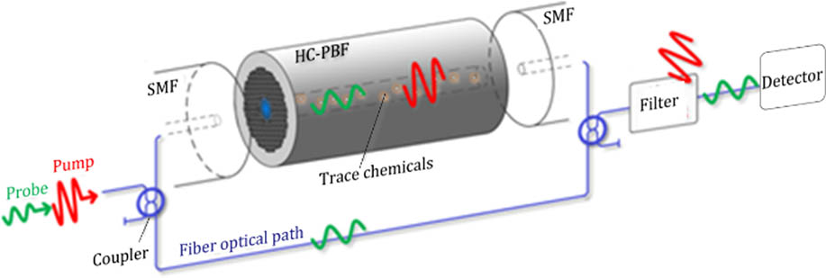
The hollow-core photonic bandgap fibers (HC-PBF), by virtue of the cellular structure, are especially suited for liquid or gas sensing[44]. The HC-PBF can simultaneously serve as light transmission cables and sensing elements with a long length. The experimental setup for detecting gas with HC-PBF is shown in Fig. 15. The configuration is an optical fiber MZI with a sensing arm formed by HC-PBF and a reference arm made by SMF, respectively. The HC-PBF acts as the gas cell filled with tracer gas with each end fusion-spliced to SMFs. The pump light and the probe light are jointly launched into the system for inducing the photothermal (PT) effect and modulating the accumulated phase, respectively. When the pump light beam is launched into the gas-filled HC-PBF, it interacts with the gas molecules generating localized heating. Thus, the local properties of the filled gas, like density, pressure, and temperature, are modulated. The transverse and longitudinal dimensions of the HC-PBF are also perturbed by the modulation. At the same time, the accumulated phase of the probe light is modulated. Then at the output of the MZI, the probe light is detected with the pump light is filtered. The concentration of the gas molecules was demonstrated as proportional to the phase modulation. Consequently, the HC-PBF integrated gas sensing system can realize a sensing concentration of 2 × 10−9[45].

Fig. 15. Hollow-core photonic bandgap fiber photothermal gas sensing system.

下载图片 查看所有图片

5. CONCLUSIONS

The refractive index microstructure waveguide fiber is a vital research field of fiber optics. Compared with traditional optical fiber, its structure is a big difference, with so many new functions and new features added. These features can be used not only for optical information processing and optical communication devices, but also can be used in the in-fiber integrated optics. The purpose of in-fiber integrated optics is to realize the miniaturization of fiber-based optical devices; it makes optical information transmission, sensing, exchanging, and processing devices more compact. This emerging photonics integration technology is evolving into a new branch of micro and nano photonics. The main concept of the in-fiber integrated optics is to integrate the optical path and various optical components into a single optical fiber. Here, we remark on the basic in-fiber integrated technology including multicore microstructured fiber, in-fiber integrated optical devices, and some application examples to explain this emerging photonics integration methodology. Varied applications can be found in micro/nano optics integration systems.

References

[1] MillerS. E., Bell Labs Tech. J.48, 2059 (1969).

[2] SomekhS. Y., in International Telemetering Conference Proceedings (1972).

[3] HillK. O.FujiiY.JohnsonD. C.KawasakiB. S., Appl. Phys. Lett.32, 647 (1978).APPLAB0003-6951

[4] InaoS.SatoT.HondoH.OgaiM.SentsuiS.OtakeA.YoshizakiK.IshiharaK.UchidaN., in Proc. Int. Wire Cable Symp. (1979), p. 370.

[5] KishiN.YamashitaE., in Microwave Symposium Digest, IEEE (1988), p. 739.

[6] CheoP. K., Proc. SPIE5335, 106 (2004).

[7] HayashiT.TaruT.ShimakawaO., Opt. Express19, 16576 (2011).OPEXFF1094-4087

[8] MatsuoS.TakenagaK.ArakawaY.SasakiY.TaniagwaS.SaitohK.KoshibaM., Opt. Lett.36, 4626 (2011).OPLEDP0146-9592

[9] TottoriY.KobayashiT.WatanabeM., in Photonics Society Summer Topical Meeting Series (2012), p. 232.

[10] KlausW.SakaguchiJ.PuttnamB. J.AwajiY.WadaN.KobayashiT.WatanabeM., IEEE Photon. Technol. Lett.24, 1902 (2012).IPTLEL1041-1135

[11] YuanL.YangJ.LiuZ., IEEE Sens. J.8, 1114 (2008).ISJEAZ1530-437X

[12] FanL. Y.JiangW. W.ZhaoR. F.PeiL.JianS. S., Opt. Precis. Eng.19, 1 (2011).

[13] ZhuB.TaunayT. F.YanM. F.FiniJ. M.FishteynM., Opt. Express18, 11117 (2010).OPEXFF1094-4087

[14] ChristodoulidesD. N.LedererF.SilberbergY., Nature424, 817 (2003).

[15] YuanL.DaiQ.TianF.ZhangT.GuanC.ZhuX., Opt. Lett.34, 1531 (2009).OPLEDP0146-9592

[16] DengH.YuanY.YuanL., Sci. Rep.7, 5171 (2017).SRCEC32045-2322

[17] DengH.YuanY.YuanL., Opt. Lett.41, 824 (2016).OPLEDP0146-9592

[18] RindorfL.JensenJ. B.DufvaM.PedersenL. H.HøibyP. E.BangO., Opt. Express14, 8224 (2006).OPEXFF1094-4087

[19] MonroT. M.BelardiW.FurusawaK.BaggettJ. C.BroderickN. G. R.RichardsonD. J., Meas. Sci. Technol.12, 854 (2001).MSTCEP0957-0233

[20] LiuS.WangY.HouM.GuoJ.LiZ.LuP., Opt. Express21, 31690 (2013).OPEXFF1094-4087

[21] BouwmansG.LuanF.KnightJ. C.RussellP. S. J.FarrL.ManganB. J.SabertH., Opt. Express11, 1613 (2003).OPEXFF1094-4087

[22] LeeB.RohS.ParkJ., Opt. Fiber Technol.15, 209 (2009).1068-5200

[23] YuanL.YangJ.LiuZ.SunJ., Opt. Lett.31, 2692 (2006).OPLEDP0146-9592

[24] YangJ.YuanL.LiuZ., Opt. Lett.31, 3237 (2006).OPLEDP0146-9592

[25] YuanL.YangJ.GuanC.DaiQ.TianF., Opt. Lett.33, 578 (2008).OPLEDP0146-9592

[26] LiuZ.BoF.WangL.TianF.YuanL., Opt. Lett.36, 2435 (2011).OPLEDP0146-9592

[27] ZhouA.ZhangY.LiG.YangJ.WangY.TianF.YuanL., Opt. Lett.36, 3221 (2011).OPLEDP0146-9592

[28] YangX.YuanT.YangJ.DongB.LiuY.ZhengY.YuanL., Opt. Lett.38, 3433 (2013).OPLEDP0146-9592

[29] YuanL.LiuZ.YangJ.GuanC., Appl. Opt.47, 3307 (2008).APOPAI0003-6935

[30] ZhaoY.ZhouA.OuyangX.OuyangY.ZhouC.YuanL., J. Lightwave Technol.35, 5473 (2017).JLTEDG0733-8724

[31] KlirosG. S., J. Optoelectron. Adv. M.5, 193 (2011).

[32] KoppV. I.ParkJ.WlodawskiM.HubnerE.SingerJ.DanN.GenackA., J. Lightwave Technol.33, 653 (2014).

[33] FlockhartG. M. H.MacphersonW. N.BartonJ. S.JonesJ. D. C.ZhangL.BennionI., Opt. Lett.28, 387 (2003).OPLEDP0146-9592

[34] KongJ.ZhouA.ChengC.YangJ.YuanL., IEEE Photon. Technol. Lett.28, 1237 (2016).IPTLEL1041-1135

[35] SrinivasanB.JainR. K., IEEE Photon. Technol. Lett.12, 170 (2000).IPTLEL1041-1135

[36] MonbergE.PorqueJ.AbedinK. S.FishteynM.WestbrookP. S.KrempT.TaunayT. F., Opt. Lett.37, 4014 (2012).OPLEDP0146-9592

[37] HeR.SazioP. J. A.PeacockA. C.HealyN.SparksJ. R.KrishnamurthiM.GopalanV.BaddingJ. V., Nat. Photon.6, 174 (2012).NPAHBY1749-4885

[38] PsaltisD.QuakeS. R.YangC., Nature442, 381 (2006).

[39] YangX.YuanT.TengP.KongD.LiuC.LiE.ZhaoE.TongC.YuanL., Lab Chip14, 2090 (2014).LCAHAM1473-0197

[40] YuanT.YangX.LiuZ.YangJ.LiS.KongD.QiX.YuW.LongQ.YuanL., Opt. Express25, 18205 (2017).OPEXFF1094-4087

[41] PengF.YangJ.LiX.YuanY.WuB.ZhouA.YuanL., Opt. Lett.36, 2056 (2011).OPLEDP0146-9592

[42] YuanL.LiuZ.YangJ.GuanC., Opt. Express16, 4559 (2008).OPEXFF1094-4087

[43] YangJ.YuanL.ZhangY.LiuZ., J. Lightwave Technol.30, 1487 (2012).JLTEDG0733-8724

[44] JinW.CaoY.YangF.HoH. L., Nat. Commun.6, 6767 (2015).NCAOBW2041-1723

[45] YangF.HoH. L.JinW.TanY.LinY., Opt. Lett.42, 4712 (2017).OPLEDP0146-9592

Xiaotong Zhang, Tingting Yuan, Xinghua Yang, Chunying Guan, Jun Yang, Zhihai Liu, Hongchang Deng, Libo Yuan. In-fiber integrated optics: an emerging photonics integration technology [Invited][J]. Chinese Optics Letters, 2018, 16(11): 110601.

本文已被 1 篇论文引用
被引统计数据来源于中国光学期刊网
引用该论文: TXT   |   EndNote

相关论文

加载中...

关于本站 Cookie 的使用提示

中国光学期刊网使用基于 cookie 的技术来更好地为您提供各项服务,点击此处了解我们的隐私策略。 如您需继续使用本网站,请您授权我们使用本地 cookie 来保存部分信息。
全站搜索
您最值得信赖的光电行业旗舰网络服务平台!