基于数字微镜器件的面源目标模拟实验系统研究  下载: 1021次
Source Simulation Experimental System Based on Digital Micromirror Device
1 中国科学院国家天文台空间天文技术实验室, 北京 100101
2 中国科学院大学, 北京 100049
图 & 表
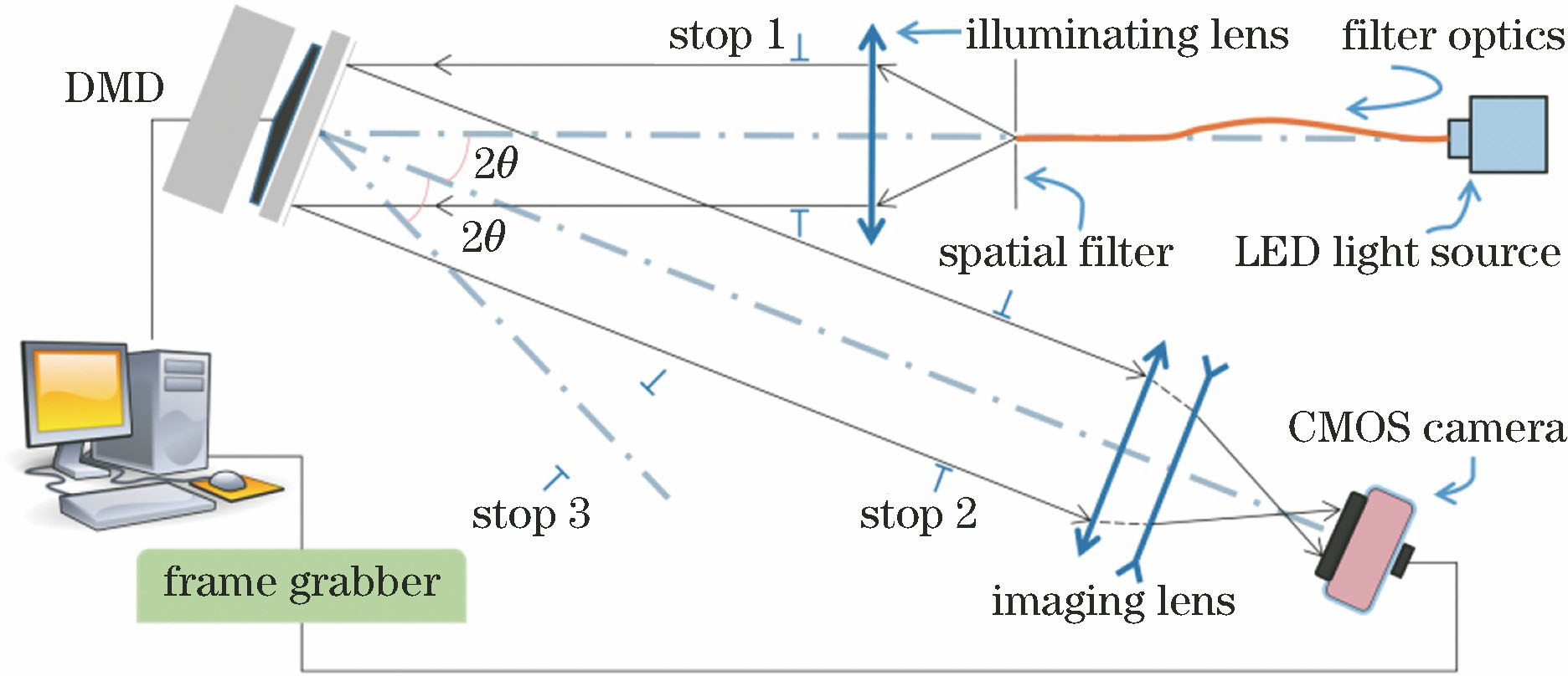
图 1. 基于DMD的目标模拟系统结构简图
Fig. 1. Structural diagram of source simulation system based DMD
下载图片 查看原文
图 2. 实验系统成像性能。(a) MTF曲线;(b)场曲和畸变
Fig. 2. Imaging performance of experimental system. (a) MTF curve; (b) field curvature and distortion
下载图片 查看原文
图 3. DMD在成像光路中的姿态。(a) DMD阵列面垂直于照明光轴;(b) DMD阵列面垂直于成像光轴;(c) Bi、Bj间距示意图
Fig. 3. DMD's azimuth in the imaging light path. (a) DMD array plane perpendicular to the lighting optical axis; (b) DMD array plane perpendicular to the imaging optical axis; (c) diagram of distance between Bi and Bj
下载图片 查看原文
图 4. DMD在光学平台上旋转45°的安装姿态
Fig. 4. DMD mounted on optical platform with rotation angle of 45°
下载图片 查看原文
图 5. Zemax非序列模式中仿真系统Shaded 模型图
Fig. 5. Shaded model diagram of simulation system with Zemax non-sequence mode
下载图片 查看原文
图 6. 畸变测量模板
Fig. 6. Distortion measurement template
下载图片 查看原文
图 7. 不同照明光源下的畸变曲线。(a)平行光源照明;(b)理想平行光源照明;(c)非平行光源(点光源沿轴移动-1 mm后所得)照明;(d)非平行光源(点光源沿轴移动+1 mm后所得)照明
Fig. 7. Distortion curves with different lighting sources. (a) Parallel source lighting; (b) ideal parallel source lighting; (c) non-parallel light source lighting (after point light source moving -1 mm along the axis); (d) non-parallel light source lighting (after point light source moving +1 mm along the axis)
下载图片 查看原文
图 8. DMD俯仰角偏差、方位角偏差、转动角偏差对不同视场畸变的影响
Fig. 8. DMD pitch angle deviation, azimuth angle deviation, and roll angle deviation as functions of distortion in different FOVs
下载图片 查看原文
图 9. 基于DMD的目标模拟系统。(a)实验光路图;(b)畸变测量实验的采集图像
Fig. 9. Source simulation experimental system based on DMD. (a) Experimental light path; (b) collected image in distortion measurement experiment
下载图片 查看原文
图 10. 实验系统畸变曲线
Fig. 10. Distortion curve of experimental system
下载图片 查看原文
图 11. 对比度测试黑白图。(a) DMD输入图;(b) CMOS采集图
Fig. 11. Black and white grid images used to test contrast. (a) Input image of DMD; (b) acquired image of CMOS
下载图片 查看原文
表 1实验系统主要光学参数
Table1. Main optical parameters of experimental system
| Parameter | Value |
|---|
| Wavelength /nm | 617 | | Effective focal length /mm | 201.8440 | | Object distance /mm | 966.6993 | | Image distance /mm | 252.2860 | | F number | 15.0048 | | Transverse magnification β | -0.2630 | | FOV /(°) | 1.0378 | | Entrance pupil diameter /mm | 17.5104 | | Total track /mm | 233.3776 |
|
查看原文
表 23个视场对应特征点表
Table2. Table of feature points corresponding to three FOVs
| FOV /(° ) | Feature point No. | Distance from center point /pixel |
|---|
| 0.5 | 6,7,8,11,13,16,17,18 | 160 | | 0.7 | 3,4,5,10,14,19,20,21 | 320 | | 1 | 1,2,9,15,22,23 | 480 |
|
查看原文
表 3系统设计、系统仿真与实验的畸变表
Table3. Distortion of system design, system simulation, and experiment
| FOV /(° ) | Imaging distortion /pixel |
|---|
| System design | Simulation | Experiment |
|---|
| 0.5 | 0.0108 | 0.1061 | 0.0761 | | 0.7 | 0.0217 | 0.1048 | 0.1783 | | 1 | 0.0312 | 0.1165 | 0.4750 |
|
查看原文
陈雪旗, 姜爱民. 基于数字微镜器件的面源目标模拟实验系统研究[J]. 光学学报, 2019, 39(10): 1011003. Xueqi Chen, Aimin Jiang. Source Simulation Experimental System Based on Digital Micromirror Device[J]. Acta Optica Sinica, 2019, 39(10): 1011003.


 PDF全文
PDF全文

