Photonics Research, 2013, 1 (1): 01000001, Published Online: Jul. 17, 2013
Self-configuring universal linear optical component [Invited]  Download: 934次
Figures & Tables
Fig. 1. Schematic illustration of the self-configuring device. Diagonal gray rectangles are controllable reflectors. Vertical clear rectangles are controllable phase shifters. Dashed clear rectangles are optional phase shifters that may be present in the implementation, but are not necessary. Configurations for (a) one input and output beam pair, (b) two beam pairs, and (c) all four possible beam pairs.
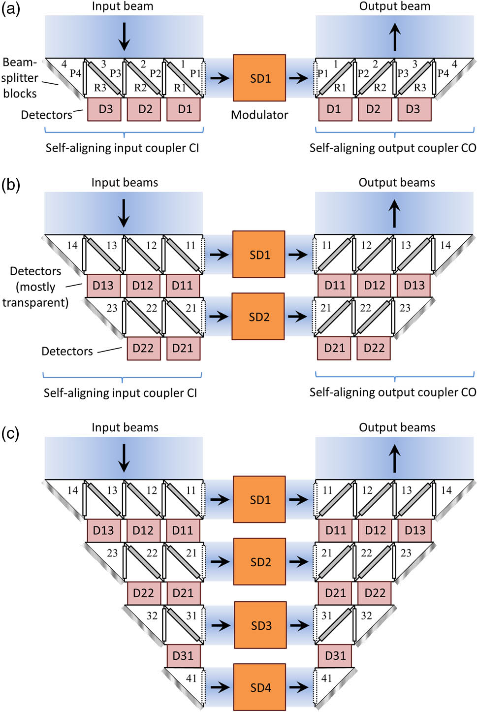
Fig. 2. Example planar layout of a device analogous to Fig. 1(c) with MZIs providing the variable reflectivities and the phase shifts. Not shown are devices, such as grating couplers, that would couple different segments of the input and output beams into and out of the waveguides WI1–WI4 and WO1–WO4, respectively. The self-aligning output coupler CO is reflected about a horizontal axis compared to Fig. 1(c) for compactness. Grayed arms of MZIs M14, M23, and M32 in both the input (CI) and the output (CO) self-aligning couplers are optional; these devices are operated only as phase shifters and could be replaced by simple phase shifters.

Fig. 3. Polarization converter. (a) Plan view. (b) Perspective view. Light incident on the grating coupler in self-aligning coupler CI is split by its incident polarization into the two waveguides, and similarly light from the waveguides going into the grating coupler in self-aligning coupler CO appears on the two different polarizations on the output light beam. PI and PO are phase shifters; the similar but grayed boxes are optional dummy phase shifters. Optionally, a phase shifter and its dummy partner could instead be driven in push–pull to double the available relative phase shift. MZI and MZO are Mach–Zehnder interferometers, and DI and DO are detectors.

Fig. 4. Red–blue interference device. A mixture of “red” and “blue” light at the input is split into its “red” and “blue” components by a dichroic beam splitter. Then the “red” component is converted to “blue” by a frequency shifter so both components are represented by “blue” light but in different waveguides. The device can be trained to look for any particular combination of “red” and “blue” and to output any particular combination of “red” and “blue” as a result.

Fig. 5. Example general apparatus for performing arbitrary linear mappings from input fields with spatial, polarization and frequency content to corresponding output fields, illustrated here for four spatial modes and three different frequency components. Each of the resulting 4 × 2 × 3 = 24 D diag

Fig. 6. Mode transformer for the operator U † M = 4

Fig. 7. Beam splitter with definitions of field reflection and transmission factors and nominal labels of the beam-splitter ports as top, bottom, left, and right.

Fig. 8. Symmetric Mach–Zehnder waveguide modulator configuration with 50% (“3 dB”) splitters notionally implemented here with coupled waveguides and two arms each with a phase-shifting element. The gray rectangles represent the phase-shifting control elements (e.g., electrodes). The labeling of the ports corresponds with the notation used in Fig. 7 .

Fig. 9. Use of optical circulators with forward and backward modes. (a) Schematic of a three-port optical circulator. The dashed lines show the effective paths of waves in different directions between the three ports. (b) Universal four-port “two-way”, potentially nonreciprocal device, with input and output beams in each of two paths at both the left and right of the device. The central U † D diag V 1 , 2 , and 5 .

Fig. 10. Illustration of an idealized time-delay unit. The switches rotates through positions 1, 2, and 3, with a dwell time of Δ t 3 Δ t

David A. B. Miller. Self-configuring universal linear optical component [Invited][J]. Photonics Research, 2013, 1(1): 01000001.


 PDF全文
PDF全文

