Photonics Research, 2021, 9 (2): 02000243, Published Online: Feb. 2, 2021
Dual-comb spectroscopy resolved three-degree-of-freedom sensing Download: 610次
Figures & Tables
Fig. 1. (a) Schematic of the experimental setup. FC1–FC3, fiber collimator, the collimated beam diameter is ∼ 3 mm ; FS, 1 × 3 fiber splitter; R, reflection mirror; BS1–BS4, nonpolarizing beam splitter; C, corner cube; BPF1 and BPF2, band-pass filter, the bandwidth is 5 nm to avoid spectral aliasing; LPF1 and LPF2, low-pass filter from 0 to f r 2 / 2 ; L1 and L2, focusing lens; PD1 and PD2, photodetector (model: 1811-FS, Newport). Diffracted beams with various frequency modes are focused by the lens and then sampled by the PD. The f ceo of both OFCs are fully stabilized by f − 2 f interferometers (f ceo 1 = f ceo 2 = 10.56 MHz ). (b) The transmission grating is tightly attached to the front surface of the corner cube. The zeroth-order diffracted beam, two first-order diffracted beams in the x direction, and two first-order diffracted beams in the y direction exit the GCC sensor parallel to the incident beam after being twice diffracted by the grating and once reflected by the corner cube. The GCC sensor in y − z view is also depicted. (c) Data processing in dual-comb interferometry. Two IGMs, I Y + 1 and I Y − 1 , with a measurement period of 1 / Δ f r . The amplitude and phase spectra of the IGMs can be calculated by FFT.
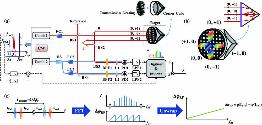
Fig. 2. Theoretical model of the present method. (a) Schematic diagram of the GCC sensor in the space coordinate system. (b) Simulated Δ φ ( 0 , ± 1 ) versus α x and α y . Simulated Δ φ ( ± 1 , 0 ) versus α x and α y . The grating pair spacing l = 97.46 mm , g = 5 μm , n i ′ = 1.5 , n i = 1 , and f i = 191.208 THz . (c) Simplified theoretical model. f i denotes the frequency of the i th longitudinal mode. ξ i ( 0 , + 1 ) and ξ ′ i ( 0 , + 1 ) are the diffraction angles of the (0, + 1 )-order diffracted beam before and after rotation, respectively. (d) Principle of angle measurement method associated with the near-infrared (NIR) frequency comb. ξ i denotes the diffraction angle of the i th longitudinal mode, f i . T r 1 denotes the repetition period of Comb 1.
Fig. 3. Precision (Allan deviation) versus averaging time, computed from 2 s length data. Both the TOF and CWI measurement results of angle and absolute distance are given. The half-unambiguity angle is 3.91 arcsec [calculated by 1.2441 × π from Eq. (12 )]. The half-unambiguity distance is a quarter-carrier wavelength (λ c / 4 ).
Fig. 4. (a) Pitch angles (α x ) obtained via the proposed method versus those obtained via the commercial autocollimator. (b) Yaw angles (α y ) obtained via the proposed method versus those obtained via the commercial autocollimator.
Fig. 5. Dynamic and resolution results. (a) Resolution results of distance under 10 Hz modulation at ∼ 1.12 m . (b) Resolution results of angle under 10 Hz modulation at ∼ 1.12 m . (c) Resolution results of distance under 25 Hz modulation at ∼ 11.35 m . (d) Resolution results of angle under 25 Hz modulation at ∼ 11.35 m .
Siyu Zhou, Vunam Le, Shilin Xiong, Yuetang Yang, Kai Ni, Qian Zhou, Guanhao Wu. Dual-comb spectroscopy resolved three-degree-of-freedom sensing[J]. Photonics Research, 2021, 9(2): 02000243.