Photonics Research, 2019, 7 (3): 03000246, Published Online: Feb. 20, 2019
Conversion between polarization states based on a metasurface  Download: 695次
Figures & Tables
Fig. 1. (a) Structure of the polarization converter consisting of rectangular holes equivalent to polarizers, and transmitted fields for (b), (c) a single rectangular hole and (d)–(f) this polarization converter.
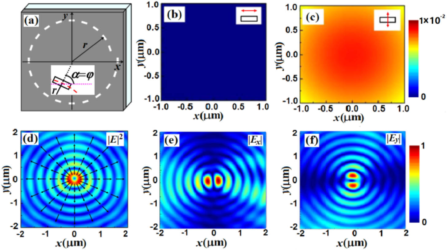
Fig. 2. (a) Structure of the polarization converter based on rectangular holes equivalent to quarter-wave plates, and transmitted intensity distributions for (b), (c) a single rectangular hole and (d)–(f) the polarization converter. The inserted patterns in (b) and (c) are the phase distributions.

Fig. 3. (a) Structure of the third polarization converter based on the cross holes equivalent to half-wave plates, and (b), (c) transmitted phase distributions for a single cross hole and (d)–(f) the intensity distributions of the polarization converter.

Fig. 4. (a) Experiment setup, (b) SEM image of the polarization converter, and (c)–(h) its transmission fields, where QWP denotes the quarter-wave plate, P1 and P2 are polarizers, S represents the sample, and MO denotes the microscopy objective. The inserted red arrows in (c) and (f) denote the incident polarization direction, and the white ones in (d)–(h) denote the direction of polarizer P2.

Shuyun Teng, Qi Zhang, Han Wang, Lixia Liu, Haoran Lv. Conversion between polarization states based on a metasurface[J]. Photonics Research, 2019, 7(3): 03000246.


 PDF全文
PDF全文

