Photonics Research, 2017, 5 (3): 03000194, Published Online: Oct. 9, 2018
Effects of the slot width and angular position on the mode splitting in slotted optical microdisk resonator  Download: 887次
Figures & Tables
Fig. 1. (a) Electric field distribution of resonator. (b) Electric field distribution of the slotted resonator.
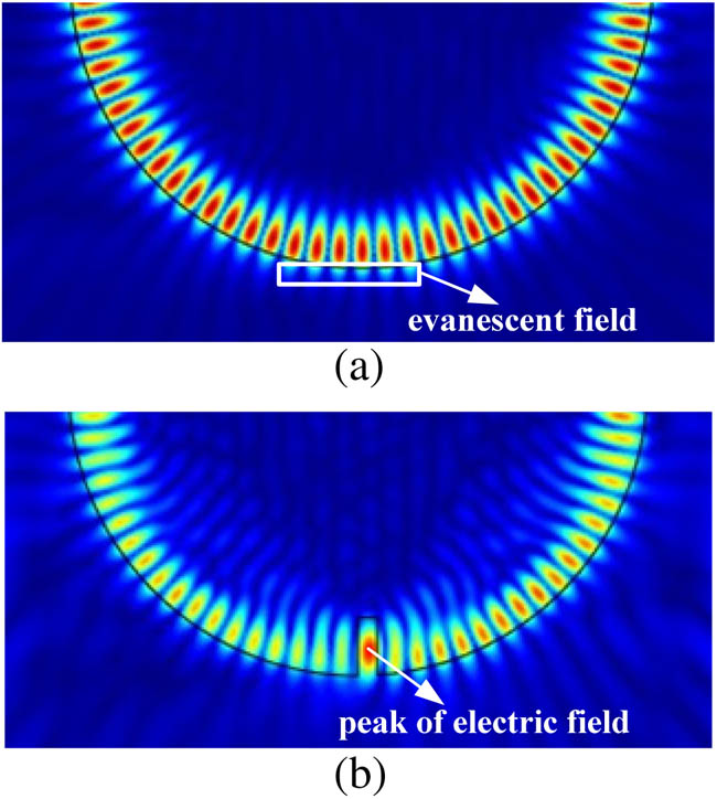
Fig. 2. Schematic of the optical WGM microdisk resonator with a single slot. a in a CW out a CCW out

Fig. 3. Schematic representation of Δ r ( φ ) φ θ

Fig. 4. Normalized transmission of the theory model (red solid line) and FEM simulation (blue dash–dot line) with the slot width of 220 nm and the slot angular position of 0°. The close agreement between the theoretical and simulation result is obtained with κ 0 = 1.211 × 10 11 Hz Γ = 1.65 κ 0 κ ex = 1.78 κ 0 γ = 2.215 κ 0 γ c = 8.4 κ 0

Fig. 5. Simulation results of the normalized transmission without single slot (corresponding parameter in the theoretical model: κ 0 = 1.211 × 10 11 Hz κ ex = 1.78 κ 0 κ 0 = 1.211 × 10 11 Hz Γ = 0.4 κ 0 κ ex = 1.78 κ 0 γ = 1.59 κ 0 γ c = 1.4 κ 0 κ 0 = 1.211 × 10 11 Hz Γ = 0.7 κ 0 κ ex = 1.78 κ 0 γ = 1.74 κ 0 γ c = 3.9 κ 0 κ 0 = 1.211 × 10 11 Hz Γ = 1.4 κ 0 κ ex = 1.78 κ 0 γ = 2.09 κ 0 γ c = 7.9 κ 0

Fig. 6. (a) Normalized detuning frequency as a function of the slot width; the blue solid curve presents the theoretical results, and the red dash curve depicts the simulation results. (b) Normalized linewidth broadening induced by the slot and Q

Fig. 7. (a) Normalized transmission in a slotted resonator with the slot width of 150 nm and the slot angular position of 0° (corresponding parameters in the theoretical model: κ 0 = 1.211 × 10 11 Hz Γ = κ 0 κ ex = 1.78 κ 0 γ = 1.89 κ 0 γ c = 6.1 κ 0 κ 0 = 1.211 × 10 11 Hz Γ = 0.85 κ 0 κ ex = 1.78 κ 0 γ = 1.815 κ 0 γ c = 5.8 κ 0 κ 0 = 1.211 × 10 11 Hz Γ = 0.6 κ 0 κ ex = 2 κ 0 γ = 1.8 κ 0 γ c = 3.3 κ 0


Lingling Dai, Yiheng Yin, Yanhui Hu, Biyao Yang, Ming Ding. Effects of the slot width and angular position on the mode splitting in slotted optical microdisk resonator[J]. Photonics Research, 2017, 5(3): 03000194.


 PDF全文
PDF全文

