Chinese Optics Letters, 2016, 14 (11): 110701, Published Online: Aug. 2, 2018   

Compact optoelectronic oscillator based on a Fabry–Perot resonant electro-optic modulator Download: 957次

Author Affiliations
1 State Key Laboratory of Information Photonics and Optical Communications, Beijing University of Posts and Telecommunications, Beijing 100876, China
2 State Key Laboratory of Millimeter Waves, Southeast University, Nanjing 210096, China
3 School of Science, Beijing University of Posts and Telecommunications, Beijing 100876, China
Abstract
A novel compact optoelectronic oscillator (OEO) employing a Fabry–Perot (FP) resonant electro-optic (EO) modulator is proposed and experimentally demonstrated. The resonant modulator is used as the optical storage element as well as the mode selection element, which can greatly reduce the system complexity and make the system more portable. Moreover, the optical resonance and electrical transmission response for the FP resonant EO modulator are theoretically and experimentally studied. The proposed OEO oscillates at 10 and 20 GHz in the proof-of-concept experiment, and the corresponding single-sideband phase noise can reach below 118 and 108 dBc/Hz at 1 MHz offset frequency, respectively.

Microwave oscillators have been widely used in the field of radar[1], communications[2], navigation[3], electronic warfare[4], and modern physics experiments[5]. However, as wireless communication technology rapidly develops, the traditional microwave oscillators can no longer meet the high performance requirements, such as high output frequency and low phase noise. As an excellent low phase noise radio frequency (RF) source, the optoelectronic oscillator (OEO) has been intensively investigated and has attracted great interest in recent years[69" target="_self" style="display: inline;">9]. The low phase noise OEO normally requires a long optical fiber in order to reach a high Q value. However, using long optical fiber causes small mode spacing. Many approaches have been applied to suppress the spurious modes, such as ultra-narrow RF bandpass filters (BPFs)[10,11], optical BPFs[12], injection locking[13,14], multi-loop oscillation[15,16], or photonic resonators[1720" target="_self" style="display: inline;">20]. Yet these methods also have their own drawbacks. The conventional ultra-narrow BPF is not narrow enough to filter out all spurious modes. The injection locking technique tends to limit the phase noise of the OEO due to the injected RF source. Although the multi-loop oscillation can suppress the spurious modes, it is very difficult to strictly match the loops, which could cause the instability of the system. High-Q photonic resonators, including the Fabry–Perot (FP) resonator and the whispering gallery mode (WGM) resonator, are of great value to the mode selection of the OEO. In addition, the high-Q resonator can also function as an optical energy storage element by trapping light in the resonator. In Refs. [17,18], a high-finesse FP etalon is used as the mode selector, and it can improve the frequency stability of the OEO due to its ultralow temperature dependency. However, these schemes are based on the intensity modulated optical link, which performs just like a finite impulse response microwave photonic filter. The bias voltage drift and discrete devices would make the oscillator incompatible with the temperature control module. In Ref. [16], a WGM microresonator is used to suppress the spurious modes. The frequency selectivity of the phase-modulation-based optical storage loop is not a singlet curve per free spectral range (FSR), which would be too difficult for single frequency oscillation to filter two adjacent modes. Moreover, the resonator with an external modulator would make the oscillator difficult to integrate. The same problem exists for the configuration with an electro-optic (EO) modulator placed in front of an FP resonator.

In this Letter, we proposed and experimentally demonstrated a novel compact OEO employing an FP resonant EO modulator. A high-quality FP resonator not only has the capability of storing optical energy, but also serves as a mode selector. It is relatively easy to manufacture an FP resonator and to couple the light into it when compared with a WGM resonator[21]. In addition, the integration of an FP resonator and an EO modulator helps to reduce the system complexity significantly, which also makes the oscillator more portable and compatible with a temperature control module. In the proof-of-concept experiment, the characteristics of the novel optical storage link have been theoretically and experimentally investigated. Based on the proposed compact OEO, 10 and 20 GHz signals oscillate respectively with corresponding single-sideband (SSB) phase noise below 118 and 108dBc/Hz at 1 MHz offset frequency. The phase noise performance can be further improved with the enhancement of the FP resonator’s quality factor.

Figure 1 shows the schematic diagram of the proposed OEO based on an FP resonant EO modulator. The light wave generated from the tunable laser was first sent into the built-in phase modulator. The polarization controller is used to align the light’s polarization state to the main axis of the LiNbO3 modulator driven by the oscillating RF signal. After the optical signal is converted back into the electrical domain, it will be amplified, phase shifted, and fed back into the oscillation loop via the RF chain.

Fig. 1. Schematic diagram of the proposed compact OEO. LD: laser diode; PC: polarization controller; OSA: optical spectrum analyzer; PM: phase modulator; PD: photodiode; EA: electrical amplifier; PS: phase shifter; ESA: electrical spectrum analyzer.

下载图片 查看所有图片

When the modulation frequency is a multiple of the FSR of the FP resonator, the output optical signal after oscillating in the FP–EO modulator for k times can be expressed as Ek=Ein(1R1)(1R2)R1R2k1exp(j(ωon0Lc+πVDCVπ))2k1exp(jβ)k,where Ein is the output optical field from the laser, R1 and R2 are the reflectivity of the FP resonator’s end faces, k is the number of round-trip times in the resonator, ωo is the angular frequencies of the optical carrier, n0 and VDC are the inherent refractive index and the bias voltage of the travelling waveguide EO modulator, respectively, L is the length of the resonator, c is the velocity of light, β=πVRF(t)/Vπ is the modulation index in which VRF(t) is the driven signal, and Vπ is the half-wave voltage of the internal phase modulator.

After several round trips, the total output optical field is Eout=k=1NEk,where N is the number of round-trip times. Assume that the reflectivity of the FP resonator’s end faces is the same (R=R1=R2), the corresponding electrical output signal can be expressed as Iout=γ|Eout|2,=2γR(1R)Ein21+Rcos(2ωon0Lc+πVDCVπ+πVRFcos(ωRFt)Vπ),=2γR(1R)Pin1+Rn=+Jn(β)cos(2ωon0Lc+πVDCVπ+nωRFt+nπ2),where γ is the responsivity of the photodiode, VRF and ωRF are the amplitude and angular frequency of the driving RF signal, respectively, and Pin is the optical output power of the laser. Considering the fundamental component of the output signal, the electrical transmission response of the optical storage link can be derived as Go=[γR(1R)βPin1+R(sin(ωRFt+2ωon0Lc+πVDCVπ)+sin(ωRFt2ωon0LcπVDCVπ))]2RloadVRF2/Rload,=[2γR(1R)βPin1+Rsin(ωRFt)sin(2ωon0Lc+πVDCVπ)]2RloadVRF2/Rload,=2γ2R2(1R)2β2Pin2(1+R)2sin2(2ωon0Lc+πVDCVπ)Rload2.

If the laser wavelength was set at a proper position, the gain of the optical segment would achieve maximum value, as shown in2ωon0Lc+πVDCVπ=mπ+π2,where m is an integer number. To form the oscillation state, the feedback RF segment is necessary to satisfy the gain and phase-matching conditions of the hybrid optoelectronic loop. The two stage amplifiers are used to make the loop gain exceed the loss. Theoretically, the gain of the amplifiers should satisfy Ge>1Go=(1+R)22γ2R2(1R)2β2Pin2Rload2.

The loop length can be adjusted via the phase shifter in the electrical chain, which would help to match the oscillation frequency with the frequency selection mode of the optical storage element. Assisted by the coupler, part of the oscillating signal can be sent out, while the rest would be fed back into the loop. Thanks to the frequency selection and high quality characteristic of the FP–EO modulator, the ultra-narrow RF BPF and long optical fiber coil are not required. In addition, the proposed OEO can be more compact via the integration of the phase modulator and FP resonator.

As mentioned above, the FP–EO modulator is the key part of our OEO. Both the optical resonance and electrical transmission characteristics play important roles for the energy storage and frequency selection. The corresponding measurement setups for resonance and filtering characteristics are in an open loop configuration. First, for measuring the optical power resonance, the setup consists of a frequency fine-tuning laser source with a narrow linewidth, an electrical function generator, a photodiode, and a high-speed resolution oscilloscope. The light wave generated from a 1550 nm tunable diode laser (New Focus TLB-6728) at a power level of 30 mW is injected into the FP–EO modulator (Opto Comb WTEC-01). The narrow linewidth and wide tuning resolution of the laser are 200 kHz and 0.01 nm, respectively. In addition, the tuning parameter of the laser is about 0.04 nm/V. Then the laser wavelength is scanned by driving the laser current with a 60 Hz triangular signal generated from the function generator (Tektronix AFG3151 C). As the blue line shows in Fig. 2, the corresponding period and peak-to-peak value of the control signal are 1/60 s and 2 V, respectively. Taking the tuning parameter of the laser into consideration, the tuning range and speed are 10 GHz and 9.6 nm/s, respectively. In order to characterize the FP resonator, the output optical signal coming from the resonator will be converted back to the electrical domain via a photodiode before the fast digital real time oscilloscope (Tektronix MDO4024C), which permits the analysis of the power peak lines at the FP resonance. In Fig. 2, we present the measurement results of the resonance peaks. As previously analyzed, the red curve clearly shows the 10 GHz wavelength sweep range and 2.5 GHz FSR. It is obvious that the wavelength span is broad enough to scan four full FSRs of the resonator.

Fig. 2. Laser wavelength scanning voltage and corresponding optical resonance spectrum of the FP resonator.

下载图片 查看所有图片

Second, for measuring the electrical transmission response of the optical storage element employing the FP–EO modulator, the measuring setup consists of a tunable laser diode, a photodiode, and a vector network analyzer. A narrow linewidth laser with a 40 kHz linewidth and at a power level of 14 dBm is used as the laser source. The light wave is fed into the FP–EO modulator driven by the RF signal generated from the output port of the vector network analyzer (Agilent N5244A). In addition, both the wavelength of the laser and the bias voltage of the modulator are finely tuned to meet Eq. (5) in the experiment. A polarization controller is used to align the polarization state of the light to the main axis of the EO modulator. After the optical signal is converted back into the electrical domain via the high-speed photodiode with a 3 dB bandwidth of 20 GHz, it will return to the input port of the vector network analyzer. Figure 3(a) gives the normalized electrical transmission response of the optical storage link from 4.5 to 23 GHz, and reflects that the transmission response is a periodic filter with 2.5 GHz FSR, which is equal to the optical FSR of the FP resonator. As is clearly shown, we can see that the 3 dB bandwidth of the responses centered at 10 and 20 GHz are 47 and 54 MHz, respectively. In addition, the corresponding out-of-band rejection can reach 38 and 32 dB. With the enhancement of the Q value of the FP resonator, the frequency selection characteristics would be much better.

Fig. 3. Measured transmission response of the optical link employing an FP resonant EO modulator. (a) Transmission response of the proposed optical storage link from 4.5 to 23 GHz. (b) Zoomed-in view of the response centered at 10 GHz. (c) Zoomed-in view of the response centered at 20 GHz.

下载图片 查看所有图片

The system operation principle has been theoretically described and the characteristics of the optical segment have been measured earlier. Then a proof-of-concept experiment based on the configuration in Fig. 1 is carried out to verify the proposed scheme. Based on the previous optical energy storage and frequency selection segment, an electronic feedback chain is necessary to form the oscillation loop. The RF chain mainly comprises two stage RF amplifiers, a phase shifter, and a microwave coupler.

The amplifiers are used to provide sufficient electrical gain in the loop. The gain of the first stage amplifier is about 30 dB from DC to 26 GHz; while for the second amplifier it depends on the oscillating frequency. For the 10 GHz oscillation frequency, a microwave amplifier from 9 to 12 GHz with a 25 dB gain is used, while it was replaced by another power amplifier from 18 to 22 GHz with a 30 dB gain in the 20 GHz oscillation loop. For the RF phase shifter, it is operated manually with a 900/GHz tuning parameter from DC to 26.5 GHz. By finely tuning the phase shifter and the laser wavelength, 10 and 20 GHz microwave signals can be generated, respectively. Then, for measuring the optical spectra of the proposed OEO, 10% of the optical signal from the 10 dB optical coupler is injected into the optical spectrum analyzer (Yokogawa AQ6370C). Just as shown in Fig. 4, the optical spectrum is measured both with a 5 nm span and a 0.02 nm resolution bandwidth. Figure 4 illustrates that the pump light at 1549.88 nm is the most powerful, and the optical spectra are frequency combs with 10 and 20 GHz intervals, which are equal to the oscillation frequency, respectively.

Fig. 4. Normalized optical power spectrum of the proposed compact OEO. (a) Optical spectra of (a) 10 and (b) 20 GHz oscillation loop.

下载图片 查看所有图片

Finally, the RF signal is produced by the frequency comb on a high-speed photodiode. The corresponding electrical spectrum and phase noise are taken by a 40 GHz RF spectrum analyzer (Agilent 9030A) via a fraction of the generated RF signal output from the 10 dB microwave coupler. Meanwhile, the rest of the microwave signal is fed back into the optoelectronic hybrid oscillating loop. In Fig. 5, the power spectrum of the oscillating signal is measured with different resolution bandwidths. As shown in the figure, the spectrum of the 10 GHz oscillating signal is measured with a 450 MHz frequency span and 100 kHz resolution, while the 20 GHz RF signal with a 320 MHz span and 10 kHz resolution. The output powers are 16.8 and 24.4dBm, respectively. A major cause of the power reduction is the different electrical transmission characteristic of the optical segment.

Fig. 5. (a) 10 and (b) 20 GHz Electrical power spectra of the proposed compact OEO.

下载图片 查看所有图片

The SSB phase noise performance of the proposed OEO has also been investigated. As shown in Fig. 6(a), the SSB phase noise of the 10 GHz generated signal is about 118dBc/Hz at an offset of 1 MHz while, for the 20 GHz generated signal, the SSB phase noise is about 108dBc/Hz at an offset of 1 MHz, as shown in Fig. 6(b).
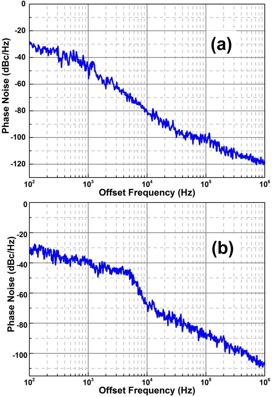
Fig. 6. SSB phase noise of the oscillation frequencies at (a) 10 and (b) 20 GHz generated by the proposed compact OEO.

下载图片 查看所有图片

The feasibility of the novel compact RF photonic oscillator has been verified. The phase noise performance is mainly limited by the Q value of the FP resonator and the noise figure of the optical storage element. By increasing the resonator’s quality factor, it can help to improve the phase noise performance of the final oscillating signal. The insertion loss of the embedded phase modulator is the main limitation of the FP resonator’s high quality factor. Finally, a stable FP resonator is useful for improving the stability of the OEO, as described in Ref. [18].

In conclusion, we propose and experimentally demonstrate a novel compact OEO employing an FP–EO modulator, which serves as both the energy storage and frequency selection elements. Due to the integration of a modulator and an FP resonator, the novel compact OEO can be realized without a long optical fiber and a large RF narrow BPF. A proof-of-concept experiment is investigated to prove the feasibility of the proposed OEO. Based on the frequency selection characteristics of the optical storage link, the OEO oscillates at 10 and 20 GHz, respectively, and the corresponding SSB noise can reach 108 and 118dBc/Hz at an offset of 1 MHz. Moreover, its performance can be greatly improved with the enhancement of the FP resonator’s quality factor.

References

[1] WangC.YaoJ. P., IEEE Trans. Microwave Theory Tech.61, 4275 (2013).IETMAB0018-9480

[2] PuertoG.MoraJ.OrtegaB.CapmanyJ., Opt. Express18, 26196 (2010).OPEXFF1094-4087

[3] EmamiH.AshourianM., IEEE Trans. Microwave Theory Tech.62, 2462 (2014).IETMAB0018-9480

[4] MorenoV.RiusM.MoraJ.MurielM. A.CompanyJ., IEEE Photonics J.5, 7101106 (2013).

[5] WeberJ., Phys. Rev.90, 977 (1953).PHRVAO0031-899X

[6] YaoX. S.MalekiL., J. Opt. Soc. Am. B13, 1725 (1996).JOBPDE0740-3224

[7] JiY.JiaX.LiY.WuJ.JinJ., Chin. Opt. Lett.11, 050602 (2013).CJOEE31671-7694

[8] YuH. C.ChenM. H.GaoH. B.LeiC.ZhangH.YangS. G.ChenH. W.XieS. Z., Photon. Res.2, B1 (2014).

[9] HuoL.YangY.LouC.GaoY., Chin. Opt. Lett.3, 140 (2005).CJOEE31671-7694

[10] WangT.LiW.ZhuN. H., Opt. Commun.318, 162 (2014).

[11] WangL. X.ZhuN. H.LiW.LiuJ. G., IEEE Photonics Technol. Lett.23, 1688 (2011).IPTLEL1041-1135

[12] LiW.LiuJ. G.ZhuN. H., IEEE Photonics Technol. Lett.27, 1461 (2015).IPTLEL1041-1135

[13] ZhouW. M.BlascheG., IEEE Trans. Microwave Theory Tech.53, 929 (2005).

[14] LeeK. H.KimJ. Y.ChoiW. Y.KamitsunaH.IdaM.KurishimaK., IEEE Photonics Technol. Lett.20, 1151 (2008).IPTLEL1041-1135

[15] YaoX. S.MalekiL., IEEE J. Quantum Electron.36, 79 (2000).IEJQA70018-9197

[16] LevyE. C.OkusagaO.HorowitzM.MenyukC. R.ZhouW.CarterG. M., Opt. Express18, 21461 (2010).OPEXFF1094-4087

[17] OzdurI.MandridisD.HoghooghiN.DelfyettP. J., J. Lightwave Technol.28, 3100 (2010).JLTEDG0733-8724

[18] BagnellM.RodriguezJ. D.DelfyettP. J., J. Lightwave Technol.32, 1063 (2014).JLTEDG0733-8724

[19] VolyanskiyK.SalzensteinP.TavernierH.PogurmirskiyM.ChemboY. K.LargerL., Opt. Express18, 22358 (2010).OPEXFF1094-4087

[20] SavchenkovA. A.IlchenkoV. S.LiangW.EliyahuD.MatskoA. B.SeidelD.MalekiL., Opt. Lett.35, 1572 (2010).OPLEDP0146-9592

[21] TavernierH.SalzensteinP.VolyanskiyK.ChemboY. K.LargerL., IEEE Photonics. Technol. Lett.22, 1629 (2010).IPTLEL1041-1135

Jian Dai, Yitang Dai, Feifei Yin, Yue Zhou, Jianqiang Li, Yuting Fan, Kun Xu. Compact optoelectronic oscillator based on a Fabry–Perot resonant electro-optic modulator[J]. Chinese Optics Letters, 2016, 14(11): 110701.

本文已被 3 篇论文引用
被引统计数据来源于中国光学期刊网
引用该论文: TXT   |   EndNote

相关论文

加载中...

关于本站 Cookie 的使用提示

中国光学期刊网使用基于 cookie 的技术来更好地为您提供各项服务,点击此处了解我们的隐私策略。 如您需继续使用本网站,请您授权我们使用本地 cookie 来保存部分信息。
全站搜索
您最值得信赖的光电行业旗舰网络服务平台!