Chinese Optics Letters, 2021, 19 (6): 060003, Published Online: Mar. 26, 2021
Integrated thin film lithium niobate Fabry–Perot modulator [Invited]  Download: 943次
Figures & Tables
Fig. 1. (a) Schematic of the resonant modulator based on LNOI. (b) Simulated optical TE0 mode profile and electric field distribution. (c) Refractive index change distribution in LN. The applied voltage is 10 V. (d) Scanning electron microscope (SEM) image of the DBR. (e) SEM image of the modulation region.
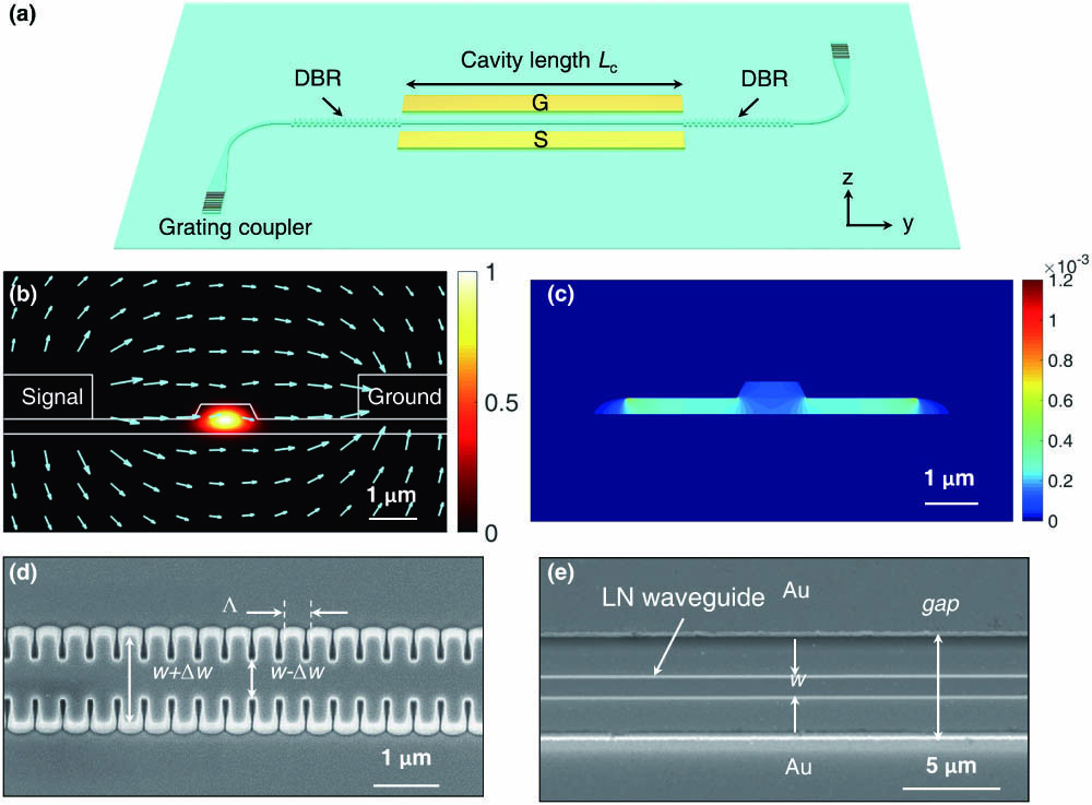
Fig. 2. Variation of the LN waveguide effective refractive index (1 V voltage applied) and absorption loss as a function of the electrode gap.

Fig. 3. (a) 1 dB bandwidth of stopband versus corrugation depth Δw. (b) Maximum extinction ratio (ER) and quality (Q) factor versus number of grating periods N. (c) Transmission spectra of the FP modulator with different FP cavity length Lc.

Fig. 4. (a) Measured transmission spectrum of the FP cavity. Inset: the resonance peak at the Bragg wavelength. (b) Measurement and linear fitting of the resonant wavelength shift as a function of the applied DC voltage. Inset: the spectral shift as the voltage sweeps from 0 V to 25 V at different wavelengths.
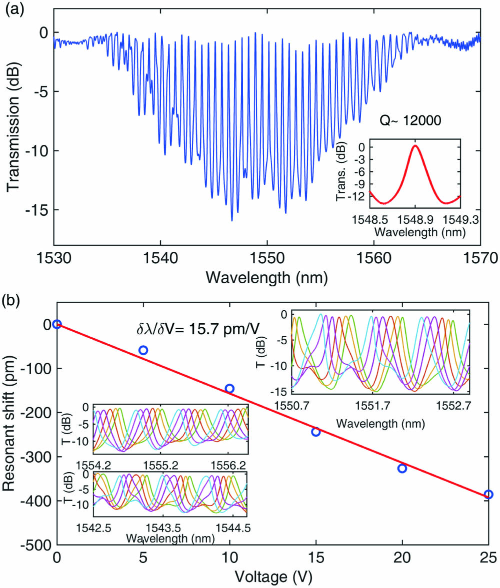
Fig. 5. Measured EO S21 responses at different operation wavelengths. Δλ represents the wavelength offset from the resonance wavelength.


Mengyue Xu, Mingbo He, Yuntao Zhu, Lin Liu, Lifeng Chen, Siyuan Yu, Xinlun Cai. Integrated thin film lithium niobate Fabry–Perot modulator [Invited][J]. Chinese Optics Letters, 2021, 19(6): 060003.


 PDF全文
PDF全文

