Dual-layered metasurfaces for asymmetric focusing  Download: 748次
1 Terahertz Technology Innovation Research Institute, Terahertz Spectrum and Imaging Technology Cooperative Innovation Center, Shanghai Key Laboratory of Modern Optical System, University of Shanghai for Science and Technology, Shanghai 200093, China
2 Shanghai Institute of Intelligent Science and Technology, Tongji University, Shanghai 200092, China
3 e-mail: ymzhu@usst.edu.cn
Figures & Tables
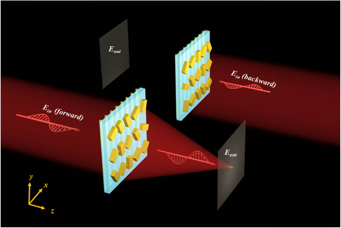
Fig. 1. Schematic of asymmetric focusing. Under the illumination of x-polarized THz waves in the forward direction, a y-polarized focal spot is observed, while the focal spot is not generated for backward x-polarized incidence.
下载图片 查看原文
Fig. 2. Design of dual-layered metasurfaces: (a1) and (a2) schematic and the corresponding geometric phase of the microrod; (b1) and (b2) schematic and the corresponding transmission spectra of the metallic gratings; (c1) and (c2) schematic and the corresponding transmission spectra of the metasurface combined with metallic gratings; (d1) and (d2) optical images of the metasurface and metallic gratings.
下载图片 查看原文
Fig. 3. (a1)–(f1) Numerical simulation of electric field distributions in the x−z plane under the illumination of x-polarized THz waves in the forward/backward direction at 0.6, 0.85, and 1.1 THz; (a2)–(f2) the corresponding electric field distributions in the x−y plane.
下载图片 查看原文
Fig. 4. (a1)–(f1) The measured electric field distributions in the x−z plane under the illumination of x-polarized THz waves in the forward/backward direction at 0.6, 0.85, 1.1 THz; (a2)–(f2) the corresponding electric field distributions in the x−y plane.
下载图片 查看原文
Fig. 5. Numerical simulation of asymmetric transmission with (a) and (b) longitudinal and (c) and (d) transversal multiple focal spots.
下载图片 查看原文
Fig. 6. (a1)–(c1) Schematics of a microrod, metallic gratings, and a unit cell of the directional device. The intersection angle between the long axis of the microrod and the x axis is 45°, while the long axis of gratings is along the x axis. (a2)–(a4) The co-polarized/cross-polarized/total transmission and reflection of the microrod under the illumination of linearly polarized THz waves. (b2)–(b4) The co-polarized/cross-polarized/total transmission and reflection of the metallic gratings under the illumination of linearly polarized THz waves. (c2)–(c4) The co-polarized/cross-polarized/total transmission and reflection of the unit cell of the directional device under the illumination of linearly polarized THz waves. Tij (Rij) is the transmission (reflection) of the i-polarized THz waves under the illumination of j-polarized THz waves (i,j=x,y). Ti (Ri,i=x,y) is the total transmission (total reflection) under the illumination of i-polarized THz waves.
下载图片 查看原文
Fig. 7. (a1)–(f1) Numerical simulation of electric field distributions in the x−z plane under the illumination of y-polarized THz waves in the forward direction at 0.6, 0.85, and 1.1 THz; (a2)–(f2) the calculated electric field distributions for backward incidence.
下载图片 查看原文
Fig. 8. The calculated and measured electric field distributions in the x−z plane under the illumination of the x-polarized THz waves from the (a1)–(f1) forward and (a2)–(f2) backward directions at 0.6, 0.85, and 1.1 THz.
下载图片 查看原文
Fig. 9. The calculated electric field distributions in the x−z plane under the illumination of the x-polarized THz waves in the (a1), (b1) forward and (a2), (b2) backward directions at 0.85 THz.
下载图片 查看原文
Fig. 10. Calculated efficiency of the directional device under the illumination of x-polarized THz waves in the forward direction.
下载图片 查看原文
Fig. 11. Schematic of multiple transmissions from the dual-layered metasurfaces.
下载图片 查看原文
Fig. 12. Comparison of the numerical (blue curves) and experimental (red curves) focusing properties: (a)–(c) the corresponding electric field distributions at x=0 in the focal plane.
下载图片 查看原文
Fig. 13. Schematics for the extinction ratio defined as (a) TEy/TEx and (b) TEy1/TEy2.
下载图片 查看原文
Fig. 14. (a1)–(c1) Calculated electric field (|Ey|2) distributions in the x−z plane under the illumination of x-polarized THz waves (with different incident angles) in the forward directions at 0.85 THz; (a2)–(c2) the calculated electric field distributions for backward incidence. Insets show the schematics for the incident THz waves with a tilted wavefront.
下载图片 查看原文
Table1. Size of the Focal Point
| Frequency (THz) | Focal Length (mm) | Focal Plane (FWHM/mm) | Plane(FWHM/mm) | | 0.6 | 2.0 | 0.296 | 0.915 | | 0.65 | 2.3 | 0.250 | 0.825 | | 0.7 | 2.5 | 0.236 | 0.775 | | 0.75 | 2.8 | 0.210 | 0.725 | | 0.8 | 3.1 | 0.204 | 0.575 | | 0.85 | 3.5 | 0.194 | 0.525 | | 0.9 | 3.9 | 0.170 | 0.545 | | 0.95 | 4.4 | 0.168 | 0.580 | | 1.0 | 4.8 | 0.166 | 0.685 | | 1.05 | 5.2 | 0.165 | 0.860 | | 1.1 | 5.7 | 0.164 | 1.150 |
|
查看原文
Table2. Comparison Between the Diffraction Limit in Theory and the FWHM of the Focal Spots
| Frequency (THz) | 0.6 | 0.85 | 1.1 | | Diffraction limit (mm) | 0.255 | 0.188 | 0.159 | | Sim. (FWHM/mm) | 0.296 | 0.194 | 0.164 | | Exp. (FWHM/mm) | 0.320 | 0.294 | 0.264 |
|
查看原文
Table3. Extinction Ratio Between and
| Frequency (THz) | 0.6 | 0.85 | 11.1 | | Sim. extinction ratio | 1.22:1 | 3.79:1 | 2.27:1 | | Exp. extinction ratio | 1.6:1 | 1.7:1 | 1.6:1 |
|
查看原文
Table4. Extinction Ratio Between the Forward and Backward Directions
| Frequency (THz) | 0.6 | 0.85 | 1.1 | | Sim. extinction ratio | 36.6:1 | 81.5:1 | 76:1 | | Exp. extinction ratio | 17:1 | 71:1 | 15.5:1 |
|
查看原文
Table5. Extinction Ratio for the Directional Device with Two Focal Spots
| Extinction Ratio | Longitudinal | Transversal | | 5.4:1 | 6:1 | | 82:1 | 38:1 |
|
查看原文
Bingshuang Yao, Xiaofei Zang, Zhen Li, Lin Chen, Jingya Xie, Yiming Zhu, Songlin Zhuang. Dual-layered metasurfaces for asymmetric focusing[J]. Photonics Research, 2020, 8(6): 06000830.


 PDF全文
PDF全文

