Chinese Optics Letters, 2017, 15 (1): 010007, Published Online: Jul. 26, 2018  

Photonic generation of background-free millimeter-wave ultra-wideband signals (Invited Paper) Download: 703次

Wei Li 1,2Ming Li 1,2Ninghua Zhu 1,2,*
Author Affiliations
1 State Key Laboratory on Integrated Optoelectronics, Institute of Semiconductors, Chinese Academy of Sciences, Beijing 100083, China
2 University of Chinese Academy of Sciences, Beijing 100049, China
Abstract
We review the recent progress of photonic generation of millimeter wave (MMW)-ultra-wideband (UWB) signals. To fully satisfy the standard defined by the Federal Communications Commission (FCC), the baseband signal (background signal) and the residual local oscillator (LO) signal should be well controlled. We discuss several schemes in this work for generating background-free MMW-UWB signals that are fully compliant with the FCC requirement.

Benefiting from low power consumption, immunity to multipath fading, carrier free, and high data rate, ultra-wideband (UWB) has attracted more and more attention for short-range high-capacity wireless communication and sensor networks[1]. The Federal Communications Commission (FCC) defined the UWB signal as a radio frequency (RF) signal that occupies a spectral bandwidth of more than 500 MHz or more than 20% fractional bandwidth with a power density no more than 41.3dBm/MHz[2]. Up to now, various approaches have been proposed to generate UWB signals in the centimeter-wave (CMW) band (3.1 to 10.6 GHz) for indoor communications[37" target="_self" style="display: inline;">7] and in the millimeter-wave (MMW) band (22 to 29 GHz) for outdoor communications[819" target="_self" style="display: inline;">19].

In this Review, we review recent progress on the photonic generation of UWB signals in the MMW band with emphasis on the generation of background-free and FCC compliant MMW-UWB pulses.

The electrical spectrum of MMW-UWB signals for outdoor communications spreads from 22 to 29 GHz. Generally, it can be realized by frequency upconversion of a baseband signal to the local oscillator (LO) band since an electrical mixer can cover this frequency range easily. Actually, the electrical mixer-based approach is more mature and easily available for us. Thus, we will first check the possibility of the electrical mixer-based approach for the generation of MMW-UWB signals.

The mixer available in our lab has an intermediate frequency (IF) bandwidth from dc to 8 GHz, an LO bandwidth from 14 to 26 GHz, and an RF bandwidth from 14 to 26 GHz. Due to the limited bandwidth of the mixer, we tried to upconvert the baseband signal to the LO band from 19 to 26 GHz that is 3 GHz lower than the FCC standard. The baseband signal has a 10 dB bandwidth of 7 GHz, while the frequency of the LO signal is 22.5 GHz.

The electrical spectrum of the upconverted signal is shown in Fig. 1(a). The baseband signal is successfully upconverted to the LO band. The generated MMW-UWB signal generally follows the FCC mask. Unfortunately, a strong LO signal can be obviously observed that is 26 dB higher than the upconverted signal. This is attributed to the poor isolation of the mixer. The corresponding waveform is shown in Fig. 1(b). The residual LO signal generates a strong sinusoidal microwave signal at both sides of the UWB waveform. The strong LO signal is hard to be eliminated using a notch filter. The power of the generated MMW-UWB signal has to be attenuated by 26 dB to avoid the interference with other wireless standards. As a result, the signal is significantly weakened and the generated UWB signal is power-inefficient[19].

Fig. 1. Measured (a) electrical spectrum and (b) waveform of the upconverted UWB signal using an electrical mixer.

下载图片 查看所有图片

It is known that the main limitation of the UWB technology is the limited transmission distance, which is around 10 m. In order to extend the transmission distance and to overcome the limitation of the electrical mixer-based approach, photonic generation of the UWB signal as well as UWB-over-fiber has been proposed[3,4]. Photonic frequency upconversion, which is similar to the electrical method, has been widely used for MMW-UWB signal generation. It has been reported that the MMW-UWB signal can be generated based on an optical parametric amplifier (OPA)[8] and four-wave mixing in a highly nonlinear photonic crystal fiber[12]. However, the signals always suffer from the residual LO signal that also exists in the electrical mixer based method.

In order to suppress the residual LO signal, we have proposed a dual-parallel Mach—Zehnder modulator (DPMZM) based a photonic MMW-UWB generator[11], as shown in Fig. 2. This structure consists of a laser diode (LD), a DPMZM, and a photodetector (PD). A baseband signal and an LO signal are combined by an electrical power combiner. The combined signal is fed to the DPMZM. The DPMZM consists of two sub-MZMs (MZM1 and MZM2). By properly setting the bias voltage of the modulator, the residual LO component can be well suppressed.

Fig. 2. MMW-UWB generator based on the DPMZM; the layout of the DPMZM is shown in the inset.

下载图片 查看所有图片

In this scheme, MZM1 is biased at the linear transmission point. Thus, the baseband signal can be upconverted to the LO band without distortion. MZM2 has no driven signal to allow the pure optical carrier to pass through. The carrier power at the MZM2 branch can be adjusted by tuning the bias voltage of MZM2. The phase difference between the two sub-MZMs is set to be 180°. by adjusting the bias voltage of the parent MZM. In this way, the optical carriers from MZM1 and MZM2 are destructively interfered with. It means that the power of the optical carrier at the output of the DPMZM can be controlled separately. The optical carrier contributes significantly to the residual LO component. The proposed method provides a new way to control the power of the LO signal.

Figure 3 shows the electrical spectra of the upconverted signal while the measured waveforms are shown in Fig. 4. The spectrum of Fig. 3(a) is obtained when MZM2 is set at the minimum transmission point (0.95 V). In this case, the optical carrier at the MZM2 branch is eliminated. The DPMZM can be regarded as a conventional MZM. The baseband signal is preset at a bit rate of 13 Gb/s with a fixed pat-tern “1110 0000 0000 0000 0000 0000 0000 0000” (three “1’s” every 32 bits). The frequency of the LO signal is 26 GHz. As can be seen from Fig. 3(a), the generated MMW-UWB signal generally fits the FCC mask. However, a strong residual LO signal still can be observed. This case is very similar to the one based on an electrical mixer, as illustrated in Fig. 1(a). The corresponding waveform is shown in Fig. 4(a). A strong sinusoidal LO signal can be observed at both data “1” and data “0.” The difference is that the LO power can be freely adjusted in this case. By properly setting the bias voltage (0.34V) as well as the power of the optical carrier at the MZM2 branch, the LO signal can be well suppressed, as shown in Fig. 3(b). The measured waveform is shown in Fig. 4(b). As can be seen, the sinusoidal LO signal only exists for data “1.” It means that the strong LO signal has been well suppressed.

Fig. 3. Measured electrical spectra of the upconverted UWB signals based on the DPMZM approach when the dc bias of MZM2 is set at (a) the minimum transmission point (0.95 V) and (b) 0.34V, respectively.

下载图片 查看所有图片

Fig. 4. Measured waveforms of the upconverted UWB signals when the dc bias of MZM2 is set at (a) the minimum transmission point (0.95 V) and (b) 0.34V, respectively.

下载图片 查看所有图片

It is worth noting that the amplitude of the generated MMW-UWB signal has been modulated using this scheme, as can be clearly seen from Fig. 4(b). The additional amplitude modulation results in a baseband signal or a background signal. In real-world applications, a bandpass filter should be added to remove the background signal, which increases the complexity of the system. In the following paragraphs, we will introduce several photonic approaches to generating a background-free MMW-UWB signal that fully agrees with the FCC mask.

The DPMZM-based MMW-UWB generator suffers from a background signal. In Ref. [16], we have demonstrated a background-free MMW-UWB generator using two cascaded polarization modulators (PolMs) and an optical bandpass filter (OBPF). The OBPF is added to realize a power balance between the optical carrier and the first-order sideband. The use of the OBPF makes the system unstable. In this section, a similar MMW-UWB generator is discussed without using an OBPF[17]. The schematic diagram of the signal generator is shown in Fig. 5. The LO and baseband signals are driven to two PolMs, respectively. Two polarization controllers (PC1 and PC2) are used to manipulate the polarization state of the light. A polarizer (Pol) can realize polarization to intensity modulation conversion. The PolM can be regarded as a special phase modulator that has opposite phase modulation indices for TE and TM modes. A sinusoidal microwave signal is fed to PolM1, and the output signal is given by EPolM1(t)=12[x^·ejω0t+jβ1cos(ωLOt)+y^·ejω0tjβ1cos(ωLOt)],where ω0 is the angular frequency of the optical carrier. β1 is the phase modulation index of PolM1, and ωLO is the angular frequency of the LO signal. Considering small signal modulation, Eq. (1) can be expressed by a Bessel function of the first kind as EPolM1(t)=12ejω0t·{x^·[J1(β1)ejωLOt+jπ/2+J1(β1)ejωLOt+jπ/2]+y^·J0(β1)},where the polarization axes of x^ and y^ are aligned with x^+45° and y^+45°, respectively. The optical carrier and sidebands are polarized at 45° and 45° relative to the x axis of the first PolM, respectively. The polarization states of the odd and even-order sidebands are orthogonal to each other.

Fig. 5. MMW-UWB generator based on cascaded PolMs.

下载图片 查看所有图片

The polarization states of the optical carrier and the first-order sidebands are aligned with the two principal axes of PolM2. In this way, an opposite phase shift is introduced to the optical carrier and sidebands. The Pol oriented at an angle of 45° to one principal axis of the PolM2 is added to combine the optical carrier and the sidebands to a fixed polarization state. The optical signal at the output of the Pol is written as Epol(t)=12ejω0t{[J1(β1)ejωLOt+jπ/2+J1(β1)ejωLOt+jπ/2]·ejβ2d(t)+J0(β1)eηjβ2d(t)},where β2 is the phase modulation index of PolM2, and d(t) is the baseband signal driven to the PolM2. For PolM, we have η=1. The photocurrent is given by i(t)Epol(t)·Epol*(t)14J02(β1)+12J12(β1)J0(β1)J1(β1)·sin[(1η)β2d(t)]·cos(ωLOt).

The photocurrent has both dc and ac parts. The dc part is constant all the time, which means that the baseband signal is eliminated. In the ac part, the LO signal is recovered for data “1,” while the LO signal is removed for data “0.” In this way, the residual LO can be well suppressed. A MMW-UWB signal can be generated as shown in the inset of Fig. 5. In this scheme, intensity modulation and phase modulation happens in turns. Actually, the MMW-UWB generator is equivalent to a high-speed microwave switch. A sinusoidal LO signal is truncated using a data signal.

In the experiment, the PolM2 was replaced by a phase modulator (PM) since only one PolM was available in our lab. For PM, we have η=1/3 rather than -1. However, the principle behind this scheme is the same. The measured waveform of the generated MMW-UWB pulse is shown in Fig. 6(a), while the corresponding electrical spectrum can be found in Fig. 6(b). The data signal was set to be 13 Gb/s with a fixed pattern “1110 0000 … 0 000” (three “1’s” every 32 bits). The frequency of the LO signal was 26 GHz. The sinusoidal microwave signal was truncated to a pulse. The UWB signal has a constant power, which means the baseband signal is removed. The background-free UWB signal is also confirmed by the electrical spectrum.
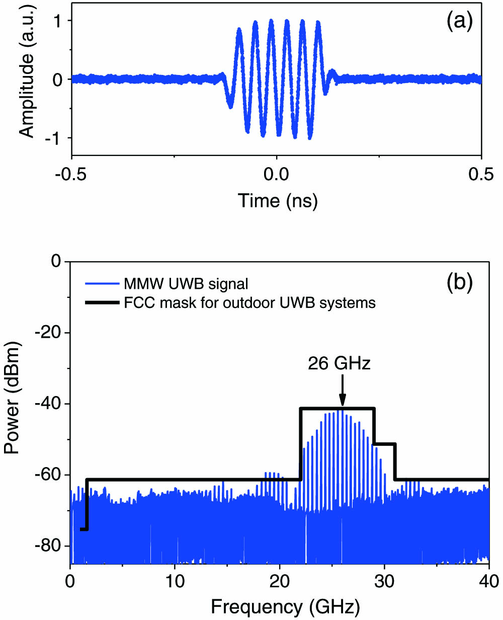
Fig. 6. Measured (a) waveform and (b) electrical spectrum of the MMW-UWB signal based on cascaded polarization modulators.

下载图片 查看所有图片

The proposed method is very promising to fully agree with the FCC standard, as shown in Fig. 6(b). The baseband signal and the residual LO signal are suppressed simultaneously, which overcomes the limitation suffered by the UWB generator using the electrical mixer and the DPMZM. However, the cascaded use of two PolMs makes the system more complicated. Moreover, many polarization-sensitive elements are exploited in the structure, which further degrades the stability of the system.

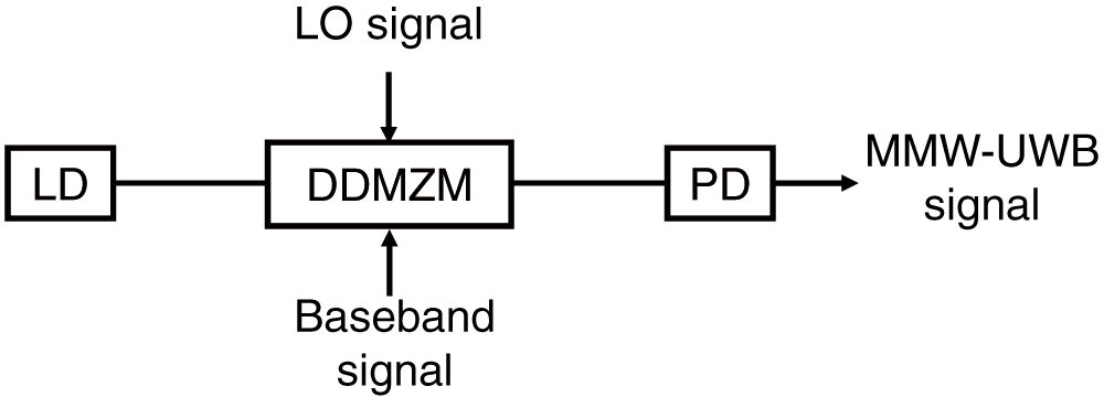
In order to enhance the stability of the system, a compact modulator is preferred. In Refs. [10,14], MMW-UWB generators using a DPMZM have been reported. However, sophisticated bias control is required, which is very complicated in practical applications. Here, we introduce an extremely simple MMW-UWB generator, see Fig. 7, that only exploits the most basic modulator, i.e., a dual-drive MZM (DDMZM)[18]. Compared to the DPMZM, the DDMZM has only one bias control. The principle behind this scheme is very similar to the one based on cascaded PolMs, but it is realized in an extremely simple way. The DDMZM has two arms; one is driven by a sinusoidal LO signal ωLO and the other one is fed by a baseband signal d(t). The output signal of the DDMZM can be expressed by E(t)=expj(ω0t+β1sin(ωLOt))+expj(ω0t+β2d(t)+φ),where ω0 is the angular frequency of the optical carrier. β1 and β2 are the phase modulation indices of the phase modulators on each arm of the DDMZM, respectively. d(t) is the peak-to-peak amplitude of the data signal and d(t)=0 or 1. φ is the static phase difference between the two arms induced by the bias of the DDMZM. After the PD, the current is given by i(t)E(t)·E*(t)=2+2cos(β1sinωLOt)cos[β2d(t)+φ]+2sin(β1sinωLOt)sin[β2d(t)+φ]=2+2J0(β1)cos[β2d(t)+φ]+4J1(β1)sin[β2d(t)+φ]sin(ωLOt).

The photocurrent consists of dc and ac signals. The dc part is related to the background signal. A background-free MMW-UWB signal means that the dc part should be constant. Thus, J0(β1)=0 and J1(β1)0 has to be satisfied. Figure 8(a) shows the amplitudes of the sidebands versus β. For β=2.4, we have J0(β1)=0 and J1(β1)=0.5. If we let φ=0, Eq. (6) is simplified as i(t)dc+sin[β2d(t)]sin(ωLOt).
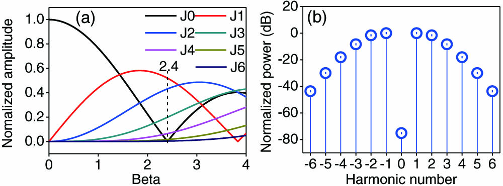
Fig. 7. MMW-UWB generator based on a single modulator.

下载图片 查看所有图片

Fig. 8. Normalized (a) amplitude of sidebands versus β and (b) power of different sidebands for β=2.4.

下载图片 查看所有图片

Figure 8(b) shows the normalized power of different sidebands for β=2.4. Equation (7) shows that the photocurrent has a constant dc part and a sinusoidal ac part whose envelope is reshaped by the data signal. If the data signal is an electrical pulse, the sinusoidal microwave signal is truncated into MMW-UWB pulses.

The principle of this idea is quite simple and an experiment is also easy to carry out to verify the possibility of the UWB generator. One arm (arm1) of the DDMZM was fed by a pulse signal that was set as a 32-bit pattern “1110 0000 … 0000” (three “1’s” every 32 bits) at a speed of 13 Gb/s. The other arm (arm2) was driven by a 26 GHz sinusoidal microwave signal. Its power was optimized to satisfy β=2.4.

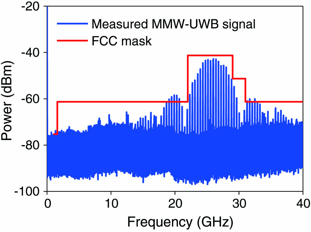
The PD used in the experiment has a bandwidth of 40 GHz. Figure 9(a) shows the generated MMW-UWB pulses. It is obvious that the average power of the pulses is constant. The zoom-in view of the pulse is shown in Fig. 9(b). The corresponding electrical spectrum of the pulse is shown in Fig. 10. The baseband signal has been totally eliminated. The MMW signal generally fulfills the FCC mask.
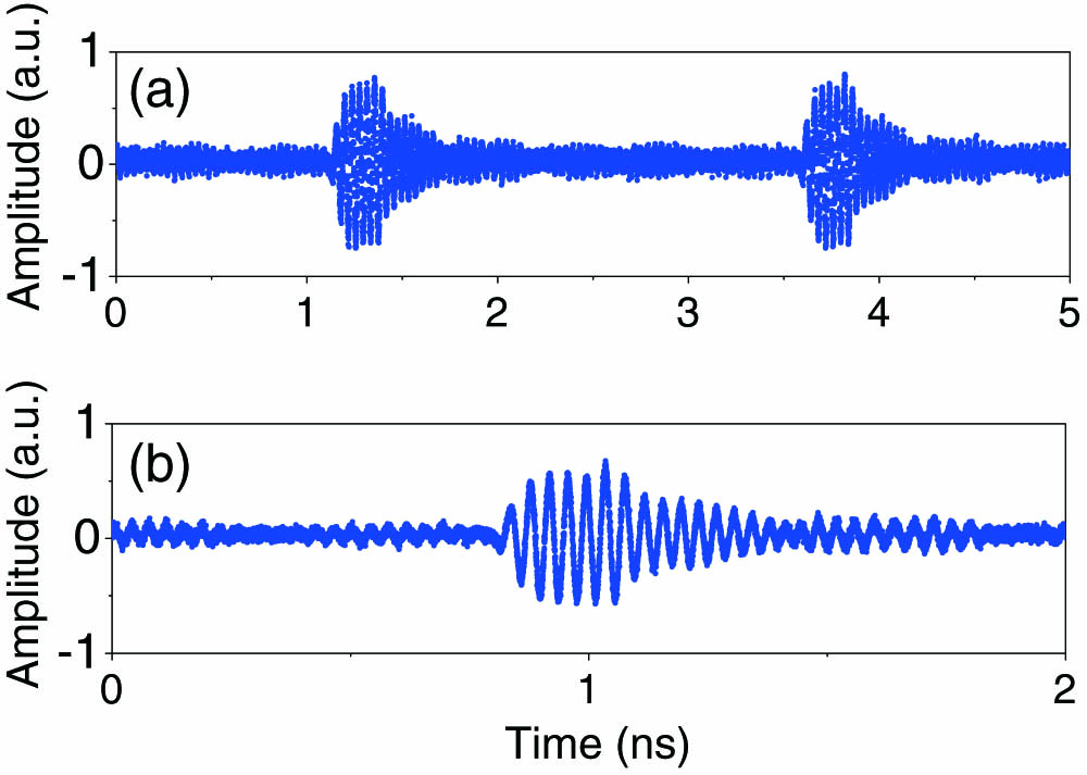
Fig. 9. Generated (a) MMW-UWB pulses and (b) the zoomed-in view based on a single modulator.
下载图片 查看所有图片

Fig. 10. Electrical spectrum of the MMW-UWB pulse as well as the FCC mask corresponding to the waveform shown in Fig. 9.

下载图片 查看所有图片

We have discussed several MMW-UWB generators in this Review. The electrical mixer-based UWB generator has strong residual LO signal that is too hard to be suppressed. Many photonic-based approaches have been proposed to overcome the limitations associated with the electrical method. We have also made many efforts to generate background-free MMW-UWB signals. The DPMZM-based approach can suppress the residual LO signal perfectly. However, the baseband signal violates the FCC standard significantly. To eliminate both the baseband signal and the residual LO signal, we used two cascaded modulators to construct a high-speed microwave switch. A sinusoidal microwave signal was truncated into pulses without changing the optical power. In this way, we successfully generated an MMW-UWB pulse that satisfies the FCC requirement. A simpler method has also been developed using a single modulator. This structure has the potential for integration, which could make the UWB generator more compact and stable. For background-free UWB signal generation, the balanced photodetection method is also an alternative way[20]. The baseband signal is eliminated by power cancellation in a balanced PD. For UWB signal transmission, signal modulation is also very important. We have reported binary phase modulation of an MMW-UWB pulse using cascaded modulators[21] or a single modulator[22]. To generate a binary phase modulated MMW-UWB pulse, a three-level electrical pulse has been used.

Similar to an optical switch, the background-free MMW-UWB generator is equivalent to a microwave switch. High-speed switching can be easily realized using a broadband modulator. The microwave switch can also be programmable by programming the data pulse. On the other hand, the MMW-UWB generator is also equivalent to a frequency upconverter. The baseband signal is upconverted to the LO band without leaking of the baseband and LO signals.

References

[1] YaoJ.ZengF.WangQ., J. Lightwave Technol.25, 3219 (2007).JLTEDG0733-8724

[2] U.S. Federal Communications Commission, “Revision of Part 15 of the commissions rules regarding ultra wideband transmission systems,” First Report and Order, ET Docket 98-153 (2002).

[3] RanM.LembrikovB. I.Ben EzraY., IEEE Photonics J.2, 36 (2010).

[4] PanS.YaoJ. P., J. Lightwave Technol.28, 2445 (2010).JLTEDG0733-8724

[5] DongJ.ZhangX.XuJ.HuangD.FuS.ShumP., Opt. Lett.32, 1223 (2007).OPLEDP0146-9592

[6] ChangY. M.LeeJ.LeeJ. H., Opt. Express18, 20072 (2010).OPEXFF1094-4087

[7] LiW.WangL. X.HofmannW.ZhuN. H.BimbergD., Opt. Express20, 20222 (2012).OPEXFF1094-4087

[8] LiJ.LiangY.WongK. K. Y., IEEE Photon. Technol. Lett.21, 1429 (2009).IPTLEL1041-1135

[9] GuennecY. L.GaryR., IEEE Photon. Technol. Lett.19, 996 (2007).IPTLEL1041-1135

[10] ChangQ.TianY.YeT.GaoJ.SuY., IEEE Photon. Technol. Lett.20, 1651 (2008).IPTLEL1041-1135

[11] LiW.WangL. X.ZhengJ. Y.LiM.ZhuN. H., IEEE Photon. Technol. Lett.25, 1875 (2013).IPTLEL1041-1135

[12] ZhangF.WuJ.FuS.XuK.LiY.HongX.ShumP.LinJ., Opt. Express18, 15870 (2010).OPEXFF1094-4087

[13] KawanishiT.SakamotoT.IzutsuM., IEEE Microwave Wireless Compon. Lett.15, 153 (2005).IMWCBJ1531-1309

[14] ZhangF.PanS., Opt. Express21, 27017 (2013).OPEXFF1094-4087

[15] DuY.ZhengJ.WangL.WangH.ZhuN.LiuJ., IEEE Photon. Technol. Lett.25, 335 (2013).IPTLEL1041-1135

[16] WangL. X.LiW.ZhengJ. Y.WangH.LiuJ. G.ZhuN. H., Opt. Lett.38, 579 (2013).OPLEDP0146-9592

[17] LiW.WangL. X.ZhengJ. Y.LiM.ZhuN. H., IEEE Photon. J.5, 5502007 (2013).

[18] LiW.WangW. T.SunW. H.WangL. X.ZhuN. H., Opt. Lett.39, 1201 (2014).OPLEDP0146-9592

[19] LiW.WangW. T.SunW. H.LiuJ. G.ZhuN. H., Opt. Express22, 10351 (2014).OPEXFF1094-4087

[20] ZhangF. Z.GeX. Z.PanS. L., Photon. Res.2, B5 (2014).

[21] LiW.WangL. X.LiM.ZhuN. H., Opt. Lett.38, 3441 (2013).OPLEDP0146-9592

[22] LiW.WangW. T.SunW. H.WangL. X.ZhuN. H., Opt. Express22, 7446 (2014).OPEXFF1094-4087

Wei Li, Ming Li, Ninghua Zhu. Photonic generation of background-free millimeter-wave ultra-wideband signals (Invited Paper)[J]. Chinese Optics Letters, 2017, 15(1): 010007.

引用该论文: TXT   |   EndNote

相关论文

加载中...

关于本站 Cookie 的使用提示

中国光学期刊网使用基于 cookie 的技术来更好地为您提供各项服务,点击此处了解我们的隐私策略。 如您需继续使用本网站,请您授权我们使用本地 cookie 来保存部分信息。
全站搜索
您最值得信赖的光电行业旗舰网络服务平台!