Chinese Optics Letters, 2018, 16 (4): 041001, Published Online: Jul. 12, 2018
Distortion correction for the elemental images of integral imaging by introducing the directional diffuser  Download: 734次
Figures & Tables
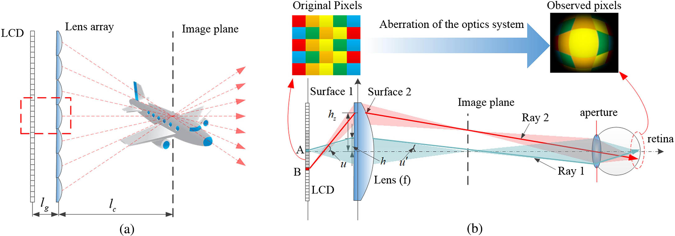
Fig. 2. Reconstructed 3D image of the integral imaging. The distances between the reconstructed images and lens array are (a) 30, (b) 60, (c) 90, and (d) 120 mm.

Fig. 3. Distortion grid maps of the separated optical system. The distances between the reconstructed images and lens array are (a) 30, (b) 60, (c) 90, and (d) 120 mm.

Fig. 4. Schematics of (a) the improved traditional II and (b) the separated optical system with the directional diffuser.

Fig. 5. Reconstructed 3D image of the II system with the directional diffuser. The distances between the reconstructed images and lens array are (a) 30, (b) 60, (c) 90, and (d) 120 mm.

Fig. 6. Distortion grid maps of the separated optical system with the directional diffuser. The distances between the reconstructed images and lens array are (a) 30, (b) 60, (c) 90, and (d) 120 mm.


Xunbo Yu, Xinzhu Sang, Xin Gao, Shenwu Yang, Boyang Liu, Duo Chen, Binbin Yan, Chongxiu Yu. Distortion correction for the elemental images of integral imaging by introducing the directional diffuser[J]. Chinese Optics Letters, 2018, 16(4): 041001.


 PDF全文
PDF全文

