外加纵向磁场对激光-MIG复合焊接接头形貌及微观组织的影响  下载: 805次
Influence of External Longitudinal Magnetic Field on Weld Joint Morphology and Microstructure in Laser-Metal Inert Gas Hybrid Welding
华中科技大学材料成形及模具技术国家重点实验室, 湖北 武汉 430074
图 & 表
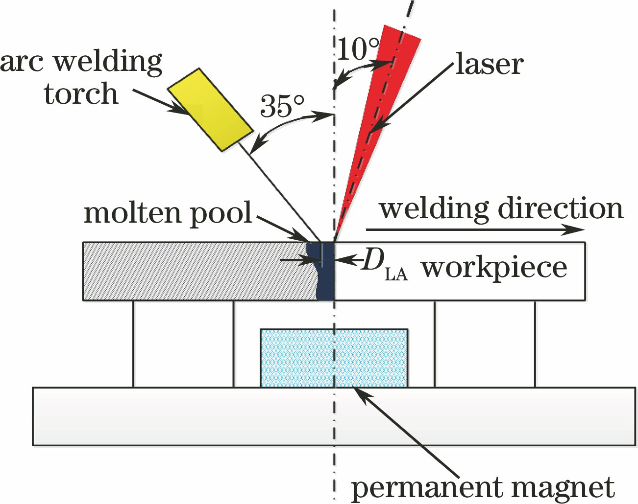
图 1. 外加纵向磁场辅助激光-MIG电弧复合焊接示意图
Fig. 1. Schematic of laser-MIG hybrid welding assisted with external longitudinal magnetic field
下载图片 查看原文
图 2. 接头显微硬度测试示意图
Fig. 2. Schematic of microhardness test of weld joint
下载图片 查看原文
图 3. 接头形貌示意图
Fig. 3. Schematic of weld joint morphology
下载图片 查看原文
图 4. 外加纵向磁场对接头形貌的影响
Fig. 4. Influence of external longitudinal magnetic field on weld joint morphology
下载图片 查看原文
图 5. 外加纵向磁场对接头成形特点的影响。(a)成形系数;(b)余高系数;(c)熔合比;(d)宽腰比
Fig. 5. Influence of external longitudinal magnetic field on weld joint forming characteristics. (a) Forming coefficient; (b) reinforcement coefficient; (c) penetration ratio; (d) width waist ratio
下载图片 查看原文
图 6. SUS316L奥氏体不锈钢母材微观组织
Fig. 6. Microstructure of SUS316L austenitic stainless steel base metal
下载图片 查看原文
图 7. 不同磁感应强度下接头的XRD图。(a) B=0 mT;(b) B=12 mT;(c) B=22 mT
Fig. 7. XRD patterns of weld joint under different magnetic induction intensities.(a) B=0 mT; (b) B=12 mT; (c) B=22 mT
下载图片 查看原文
图 8. 不同磁感应强度下接头顶部微观组织。(a) B=0 mT;(b) B=12 mT;(c) B=22 mT
Fig. 8. Microstructure of top area of weld joints under different magnetic induction intensities.(a) B=0 mT; (b) B=12 mT; (c) B=22 mT
下载图片 查看原文
图 9. 不同磁感应强度下接头中部微观组织。(a) B=0 mT;(b) B=12 mT;(c) B=22 mT
Fig. 9. Microstructure of middle area of weld joints under different magnetic induction intensities.(a) B=0 mT; (b) B=12 mT; (c) B=22 mT
下载图片 查看原文
图 10. 不同磁感应强度下接头HAZ的SEM照片。(a) B=0 mT;(b) B=12 mT;(c) B=22 mT;(d)图(c)的局部放大照片
Fig. 10. SEM images of HAZ of weld joints under different magnetic induction intensities.(a) B=0 mT; (b) B=12 mT; (c) B=22 mT; (d) partial enlarged view of Fig. 10(c)
下载图片 查看原文
图 11. EDS分析结果。(a)测试区;(b)测试点A;(c)测试点B
Fig. 11. EDS analysis results. (a) Test area; (b) test point A; (c) test point B
下载图片 查看原文
图 12. 不同磁感应强度下接头显微硬度分布,插图为对应测试区域。(a)顶部;(b)中部;(c)底部
Fig. 12. Microhardness distributions of weld joints under different magnetic induction intensities and illustrations show corresponding test areas. (a) Top; (b) middle; (c) bottom
下载图片 查看原文
图 13. 显微硬度分布的标准差
Fig. 13. Standard deviation of microhardness distribution
下载图片 查看原文
表 1母材及焊丝的化学成分(质量分数,%)
Table1. Chemical compositions of base metal and filler wire (mass fraction, %)
| Element | C | Mn | Si | S | P | Cr | Ni | Mo | Fe |
|---|
| Base metal | ≤0.03 | ≤2.00 | ≤0.75 | ≤0.030 | ≤0.045 | 16.0-18.0 | 10.0-14.0 | 2.0-3.0 | Bal. | | Filler wire | ≤0.03 | 1.0-2.5 | 0.83 | ≤0.020 | ≤0.030 | 18.0-20.0 | 11.0-14.0 | 2.5-3.0 | Bal. |
|
查看原文
表 2外加纵向磁场辅助激光-MIG电弧复合焊接参数
Table2. Parameters of laser-MIG hybrid welding assisted with external longitudinal magnetic field
| Laserpower /kW | Current /A | Welding speed /(m·min-1) | Focal pointdistance /mm | DLA /mm | B /mT |
|---|
| 2.0 | 150 | 1.1 | 0 | 2 | 0, 8, 12, 16, 22 |
|
查看原文
表 3不同磁感应强度下接头及横截面形貌
Table3. Weld joints and cross-sectional morphologies under different magnetic induction intensities
| B /mT | Weld joint morphology | Cross-sectional morphology of weld joint |
|---|
| 0 | | | 8 | | | 12 | | | 16 | | | 22 | |
|
查看原文
表 4EDS分析结果
Table4. EDS analysis results
| Element | Point A | Point B |
|---|
| Mass fraction /% | Atomic fraction /% | Mass fraction /% | Atomic fraction /% |
|---|
| Si | 0.98 | 1.94 | 0.65 | 1.29 | | Cr | 22.44 | 24.02 | 18.66 | 19.95 | | Mn | 1.22 | 1.24 | 1.76 | 1.78 | | Fe | 64.47 | 64.24 | 64.87 | 64.57 | | Ni | 6.08 | 5.77 | 11.58 | 10.97 | | Mo | 4.80 | 2.79 | 2.47 | 1.43 |
|
查看原文
张勋, 李若杨, 赵泽洋, 米高阳, 王春明, 胡席远. 外加纵向磁场对激光-MIG复合焊接接头形貌及微观组织的影响[J]. 中国激光, 2017, 44(8): 0802008. Zhang Xun, Li Ruoyang, Zhao Zeyang, Mi Gaoyang, Wang Chunming, Hu Xiyuan. Influence of External Longitudinal Magnetic Field on Weld Joint Morphology and Microstructure in Laser-Metal Inert Gas Hybrid Welding[J]. Chinese Journal of Lasers, 2017, 44(8): 0802008.


 PDF全文
PDF全文

