Design method for freeform reflective-imaging systems with low surface-figure-error sensitivity  Download: 873次
State Key Laboratory of Precision Measurements Technology and Instruments, Department of Precision Instrument, Tsinghua University, Beijing 100084, China
Figures & Tables
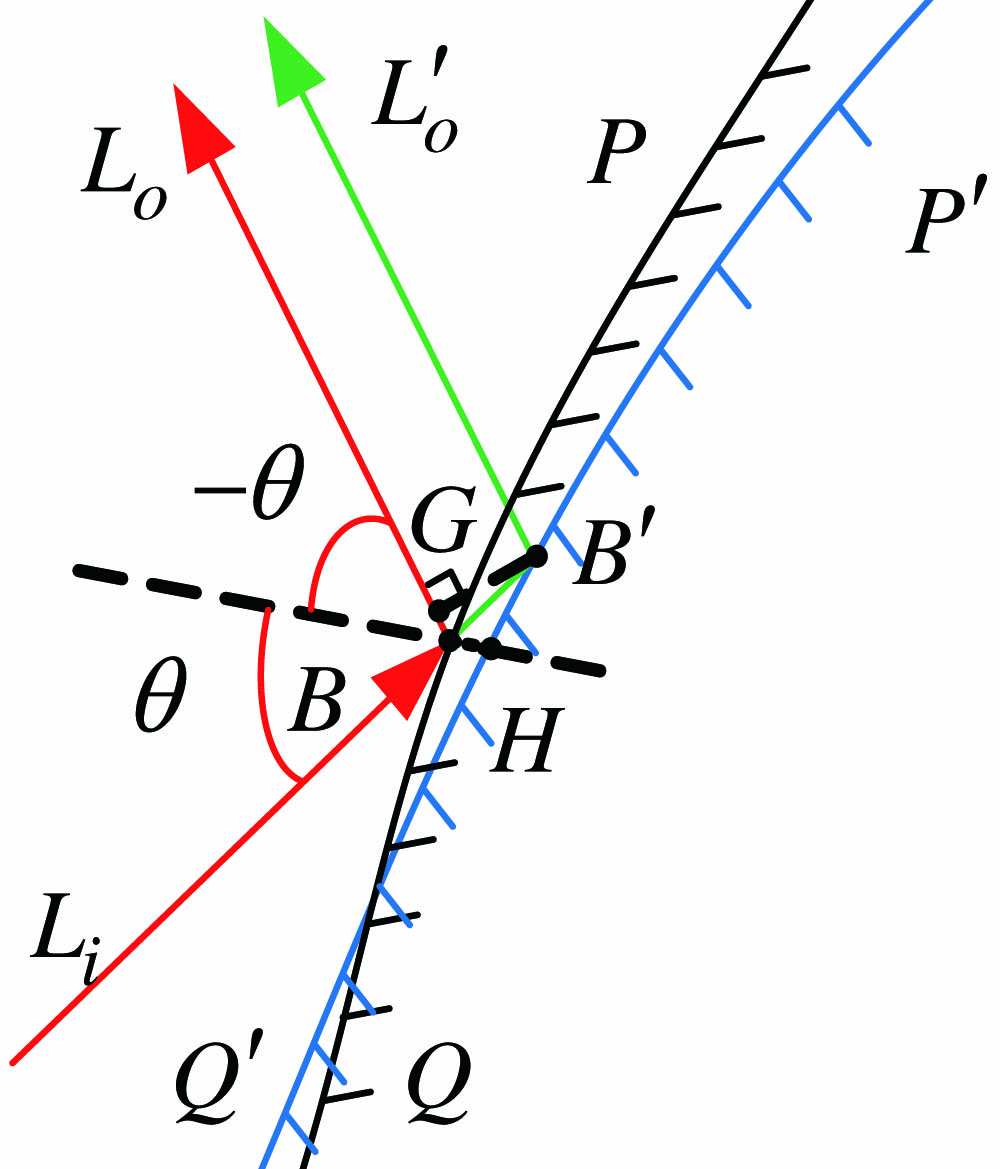
Fig. 1. Optical-path-length change caused by figure errors.
下载图片 查看原文
Fig. 2. Establish initial planar system.
下载图片 查看原文
Fig. 3. (a) Forward ray tracing; (b) reverse ray tracing.
下载图片 查看原文
Fig. 4. Shifting image points to change AOIs on the TM.
下载图片 查看原文
Fig. 5. (a) Initial planar system; (b) initial freeform surfaces system; (c) freeform surfaces system with greater than ; (d) freeform surfaces system, in which , are greater than , , respectively; (e) initial system with low surface-figure-error sensitivity, in which , , and are greater than , , and , respectively; (f) optimized system; (g) field map of the RMSWFE.
下载图片 查看原文
Fig. 6. (a) Initial planar system; (b) initial system designed by CI-3D method; (c) optimized system; (d) field map of the RMSWFE.
下载图片 查看原文
Fig. 7. Sensitivity curve of the two systems to surface figure errors. (a) PM; (b) SM; (c) TM.
下载图片 查看原文
Table1. Optical System Specifications
| Parameter | Specification |
|---|
| Field of view (FOV) | | | F-number | 1.5 | | Focal length | 100 mm | | Wavelength | 8–12 μm |
|
查看原文
Table2. Absolute AOIs on Each Surface of the Systems in Fig. 5a
| System | AOI | PM | SM | TM |
|---|
| (a) | Min | 30 | 25 | 25 | | (b) | Min | 28.34 | 21.66 | 19.25 | | (c) | Min | 30.36 | 22.49 | 19.64 | | (d) | Min | 30.36 | 25.46 | 21.60 | | (e) | Min | 30.36 | 25.46 | 25.62 | | (f) | Min | 43.58 | 51.75 | 26.27 |
|
查看原文
Yuting Deng, Guofan Jin, Jun Zhu. Design method for freeform reflective-imaging systems with low surface-figure-error sensitivity[J]. Chinese Optics Letters, 2019, 17(9): 092201.


 PDF全文
PDF全文

