Opto-Electronic Advances, 2019, 2 (4): 180022, Published Online: Apr. 28, 2019
A review of crosstalk research for plasmonic waveguides
Figures & Tables
Fig. 1. Four different waveguide schematics ((a), (b), (c), (d)) and the dependences of (e) coupling length L c and (f) maximum transfer power P max on separation distance D 23.
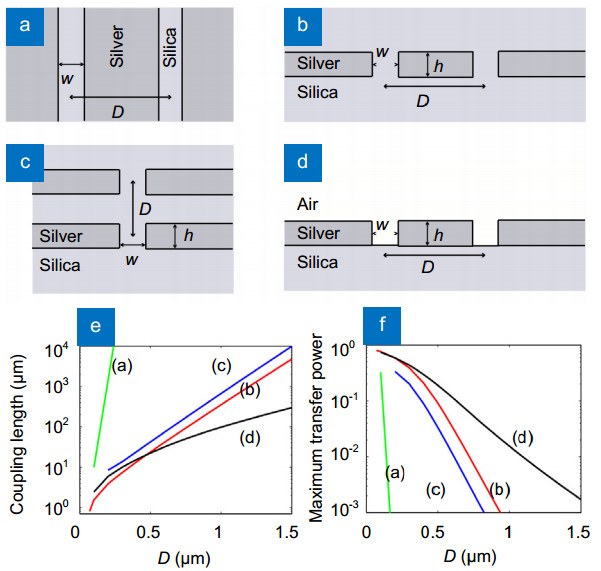
Fig. 2. (a ) The schematic of two adjacent parallel channel plasmonpolariton waveguides. (b ) The crosstalk performance with specific parameters 27.

Fig. 3. (a ) The 2D and (b ) 3D schematic diagrams of two WPP waveguides. Normalized crosstalk power of WPP waveguides under different parameters with wedge height (c ) h =0.5 μm and (d ) h =1.6 μm 32.

Fig. 4. Schematic diagrams of (a) hybrid waveguide and (b) its rotation, (c) distribution of Ey field for rotation hybrid waveguide, (d) coupling length L c and (e) maximum power transfer P max as functions of the separation D , the red solid line and blue dotted line represent the results of the two structures of (a) and (b), respectively 25.

Fig. 5. Schematic configuration of the two parallel hybrid silicon plasmonic waveguides (HSPW) (a) without and (b) with metallic strip. The maximum power transfer P max versus specific parameters (separation distance D , height h and width w of the metallic strip) (c ) without and (d ) with metallic strip 30.


Junxian Ma, Dezheng Zeng, Yatao Yang, Can Pan, Li Zhang, Haidong Xu. A review of crosstalk research for plasmonic waveguides[J]. Opto-Electronic Advances, 2019, 2(4): 180022.


 PDF全文
PDF全文
