Photonics Research, 2019, 7 (11): 11001296, Published Online: Oct. 30, 2019
Interference-enhanced optical magnetism in surface high-index resonators: a pathway toward high-performance ultracompact linear and nonlinear meta-optics Download: 502次
Figures & Tables
Fig. 1. Meta-optics based on Si resonators on a plasmonic substrate. (a) Illustration of a unit cell of the metasurface consisting of an array of a - Si : H nanodisks on top of an optically thick Au ground plane. Geometrical parameters: P = 720 nm , D = 450 nm , and h = 385 nm . (b) Schematic of the proposed meta-optical systems with finite array size, in which square arrays having m × m a - Si : H nanodisk elements are located on top of an infinite Au substrate. (c) Calculated magnetic field (| H | ) obtained from a magnetic probe located at the center of the central resonator for a series of array sizes used in numerical simulations. The gray dashed line is used to guide the eye. (d) Q -factor and the maximum enhancement factor | H | max as functions of the array size. The corresponding values in the periodic case are illustrated as well. (e)–(h) Calculated magnetic field and electric field vector distribution in the y – z plane, in the case of m = 1 , 9, and 15 as well as the periodic structure at the peak frequency identified in (c).
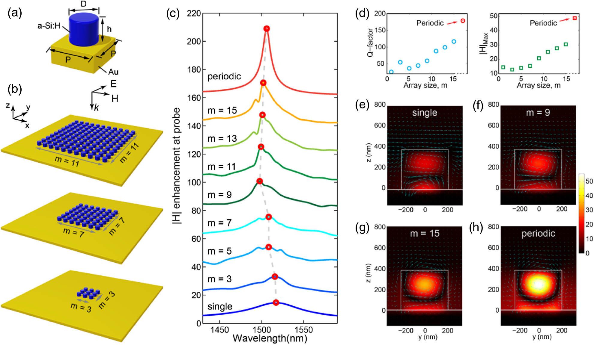
Fig. 2. All-optical ultrafast modulation enabled by critical coupling with the guided resonance of meta-optical systems. (a) Schematic of the unit cell used in numerical simulations. The geometrical parameters are the same as those used in Fig. 1(a) . The ultrafast nonlinear responses of the proposed metasurface are obtained by implementing the theoretical model presented in Ref. [38]. (b) Transient absolute reflectance modulation (Δ R ) under pumping at an 800 nm wavelength with a pump fluence of 0.1 mJ / cm 2 . The pump intensity is 10% of that used in Ref. [38]. For clarity, the results around the resonance are enlarged and shown on the right (dashed-green box). The simulated static reflectance and absorption spectra are shown in the inset. (c) Relative differential reflectance (Δ R / R ) at a few wavelengths of interest near the resonance.
Fig. 3. Polarization sensitive ultrafast modulation based on Si nanodisks with an elliptical cross-section. (a) Schematic of the unit cell used in numerical simulations. The major and minor axes of the elliptical cross-section are 500 and 450 nm, respectively. (b) The cross- and co-polarization reflectance spectra when the metasurface is illuminated by a y -polarized wave. Inset indicates the orientation of the Si nanodisk in the x – y plane. Calculated magnetic field (normalized to that of the incident wave) and its vector distribution in a plane cut across the middle of the resonator at the two resonance wavelengths (bottom). Transient absolute reflectance modulation for (c) the co-polarization reflected wave (Δ R y y ) and (f) the cross-polarization reflected wave (Δ R x y ) under pumping at an 800 nm wavelength with a pump fluence of 0.1 mJ / cm 2 . Relative differential reflectance (d), (e) (Δ R y y / R y y ) and (g) (Δ R x y / R x y ) at a few wavelengths of interest.
Fig. 4. Exploiting the magnetic response in individual high-index resonators for excitation of SPPs. (a) Schematic of the meta-optical system that includes a Si cuboid located on a gold substrate. Around the magnetic Mie resonance of the resonator, SPPs primarily propagating along the + y and − y directions will be excited on the surface of the gold substrate. A y -polarized plane wave normally illuminates the resonator from the top. A magnetic (H ) field probe is placed in the center of the cuboid, and an electric field probe is placed 10 nm above the gold surface at y = 5 μm . (b) Magnitude of E z detected at the E -field probe and (c) magnitude and (d) phase of H x detected at the H -field probe, when the SP wave is excited by a Si cuboid of two distinct geometries (Cuboid A: l = 400 nm , w = 200 nm ; Cuboid B: l = 480 nm , w = 240 nm ). For comparison purposes, the results based on a glass cuboid of the same dimensions are shown in (b)–(d) as well (dashed curves). (e), (f) The magnetic field distribution for both excitation systems at a wavelength where | E z | peaks. The electric field distribution of SPPs excited on the gold surface (g) by Cuboid A and (h) by Cuboid B.
Fig. 5. Directional excitation of SPPs using a pair of high-index resonators. (a) Schematic of the meta-optical system for directional generation of SPPs. A y -polarized plane wave normally illuminates the resonators from the top. To monitor the excited SP waves, two electric field probes are placed 10 nm above the gold surface at y = − 5 and + 5 μm , respectively. (b) | E z | detected at the two E -field probes and, (c) the corresponding ratio between | E z | at the two probes (| E z | probe 1 / | E z | probe 2 ), when the two cuboids are separated by a series of distances (Dis). (d) | E z | 2 distribution on an imaginary circle (with a radius of 10 μm) at a wavelength of 1636 nm when Dis = 450 nm and (e) the corresponding electric field distribution of SPPs excited on the gold surface. (f)–(h) | E z | 2 distributions corresponding to the | E z | ratio peaks in (c) on the imaginary circle.
Lei Kang, Huaguang Bao, Douglas H. Werner. Interference-enhanced optical magnetism in surface high-index resonators: a pathway toward high-performance ultracompact linear and nonlinear meta-optics[J]. Photonics Research, 2019, 7(11): 11001296.