1 Key Laboratory of In-Fiber Integrated Optics, Ministry of Education, College of Physics and Optical Engineering, Harbin Engineering University, Harbin 150001, China
2 Photonics Research Center, School of Electric Engineering and Automation, Guilin University of Electronics Technology, Guilin 541004, China
Figures & Tables
Fig. 1. Stable 3D optical trapping near the focus area, where the gradient force dominates the micro-particle[17].
Fig. 2. Optical fiber tip tweezers. (a) Parabola-like profile fiber tip; (b) a yeast cell trapped by fiber optical tweezers; (c) and (d) the intensity of the optical field emerging from the fiber tip[48].
Fig. 3. Trapped yeast cell transferred between two optical fiber tweezers. (a) A yeast cell first trapped by a horizontal fiber tip; (b) the yeast cell transferring from the horizontal fiber tip to the vertical fiber tip; (c) the yeast cell transferred to a fiber tip in the vertical direction.
Fig. 5. Schematic diagram of the optical fiber optical hand concept. (a) Picture of a human hand holding an egg; (b) schematic diagram of a yeast cell controlled by a micro-optical hand built by a multicore fiber.
Fig. 8. Beam combination field at/out of the focus point. (a) Schematic of a cone-shaped three-core fiber tip; (b) intensity of the output beams; (c) electric-field distribution of the output beams.
Fig. 9. Pyramid end of the four-core fiber for optical hands fabrication[42]. (a) The cross section of the four-core fiber; (b) the schematic diagram of the polished four-core fiber; (c) two trapping positions generated, respectively, by each of the two cores; (d) the trapping distance from the trapping point to the fiber end.
Fig. 10. Mode division multiplexing technology based optical tweezers. (a) Experimental setup of the optical tweezers, where the two kinds of SMFs are spliced with a defined offset, and the mode is selected by a fiber micro-bending modulator; (b) position adjustment of the particle by the optical tweezers[54].
Fig. 11. Single-fiber tweezers for particle adjustment. (a) The truncated cone-shape fiber tip fabricated by the two-step method; (b) microparticle adjusted by the LP11 mode[55].
Fig. 12. Annular-core fiber and its cone-frustum tip shape. (a) The cone-frustum end of the annular-core fiber; (b) the cross section of the annular-core fiber; (c) the focus beam from the annular core.
Fig. 13. Concept of a fiber optical gun: a coaxial core optical fiber could be used to build a microparticle trapping and shooting system[44]. (a) The cross section of the CCF; (b) the refractive index of the CCF; (c) the particle trapped by the ring beam from the annular core and shot by the Gaussian beam from the central core.
Fig. 14. Structure of the fiber optical gun. (a) Experimental setup of the fiber optical gun; (b) laser side polishing coupling from the SMF with the annular core of the CCF; (c) the Gaussian beam from the central core and the ring beam from the annular core[58].
Fig. 15. Multiparticle trapping fiber tweezers. (a) The schematic diagram of the fiber-based tweezer; (b) electron microscope image of the etched fiber tip; (c) multiple yeast cells trapped by the optical fiber tweezers.
Fig. 16. All-fiber Bessel optical tweezer. (a) The schematic diagram of the experimental setup; (b) the fabricated fiber tip; (c) three cells trapped by the focused Bessel beam[60].
Fig. 17. Noncontact optical trapping and arrangement of chloroplasts in vivo; OFP refers to the optical fiber probe. (a1) and (b1) The schematic diagram of multiparticle trapping; (a2) and (b2) photos of the multi-chloroplast trapped by the OFP; (c1) and (c2) two rows of chloroplasts arranged by the OFP[62].
 Download: 1114次
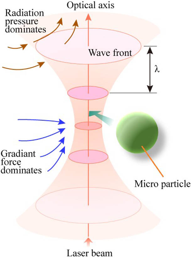


 PDF全文
PDF全文

