Interference at the single-photon level based on silica photonics robust against channel disturbance
1. INTRODUCTION
The risk of failure for classical cryptography increases as an eavesdropper’s computing power is upgraded, making information security vulnerable. Quantum key distribution (QKD) allows two remote parties (named Alice and Bob) to share secure keys, free from the eavesdropping of a third party. Its unconditional security is guaranteed by the fundamental laws of quantum physics [1]. Bennett and Brassard first proposed BB84 protocol [2] and demonstrated a short-range free-space polarization-encoded QKD setup [3]. Since polarization states are quite vulnerable to the variation of ambient environment in fiber-based transmission [4,5], qubits are practically encoded in time-bin and phase states [6]. Early QKD systems were based on bulk optics or fiber optics [7,8], which lack flexibility and suffer from phase and polarization instability. Fortunately, these problems have been successfully addressed and resolved by several research groups [9–13]. Recently, time-bin phase and polarization-encoding QKD systems based on photonic integrated circuits (PICs) have been demonstrated [14–17], dramatically miniaturizing the system. By precisely controlling the ambient conditions of chip devices both at Alice and Bob, the stability of the qubit states can be enhanced.
However, the field environment of the fiber channel is of much complexity and variation, which would severely limit the operation of a QKD system. There are two main factors hindering its long-term continuous operation. One is the variation of optical path length, and the other is the birefringence in the fiber channel. The former one can be well tracked [18] or solved by superior synchronization techniques [19,20]. The latter one becomes the major obstacle. Birefringence variations in the fiber channel dramatically decrease the interference visibility of phase states and thus increase the quantum bit-error rate (QBER) of a QKD system. The recent countermeasures against the channel disturbance can be classified into active and passive categories. Polarization basis alignment modules were proposed to actively compensate for the disturbance [21]. Passive compensation solutions are also demonstrated, such as the plug-and-play system [9], the Faraday–Michelson structure [10], the Sagnac structure [11], or a combination of both structures [12]. Although these solutions can automatically compensate for the channel disturbance, the repetition rate is limited by their structures because pulses have bidirectional transmission through the phase modulator. By contrast, one-way QKD systems based on asymmetric Mach–Zehnder interferometers (AMZIs) do not have this bidirectional transmission problem that limits the repetition rate. The shorter the time delay of AMZI, the higher repetition rates the system can achieve. NEC Corporation [22] proposed a scheme to counter channel disturbance by exerting precise temperature control on AMZI planar light circuits (PLCs). Despite of the fact that their setup shows robustness and stability, their work lacked study on the dependence of the AMZI’s delay on the full-wave temperature (the temperature variation span corresponding to a whole interference fringe), especially for the case in which the delay is relatively short. Furthermore, they did not study AMZI chips with thermo-optic phase modulators (TOPMs), which make phase modulation more energy efficient and give more reconfiguration ability to the chip.
To optimize the trade-off between countering channel disturbance and limiting the repetition rate, we present a setup comprising interferometers based on silica photonics, which shows great robustness against the channel polarization disturbance. AMZI PLCs of 200, 400, and 740 ps delay lines, integrated with a tunable power splitter and TOPMs, are designed and fabricated. Compared to the classical interference method employed in Ref. [22], a novel pulse self-interfering method is proposed to investigate at the single-photon level the polarization characteristics of the AMZI chip. The setup is devised, and its operation condition to implement channel polarization insensitivity is given. Furthermore, the dependence of the delay on the full-wave temperature is demonstrated. Over a 20 km fiber channel with 30 Hz polarization scrambling, our time-bin phase-encoding QKD setup is characterized with an interference fringe visibility of 98.72%. The extinction ratio for the phase states is kept between 18 and 21 dB for 6 h without active phase correction.
2. DESIGN AND FABRICATION OF THE AMZI PLC
We have designed and fabricated 200, 400, and 740 ps delay AMZI PLCs for a telecom (1.55 μm) wavelength window [16]. Figure 1(a) demonstrates the schematic of the chip, which consists of two parts. Part one is a tunable power splitter, which is a 2 × 2 MZI with a TOPM1 in one arm to balance the extra loss introduced by the delay line. Part two is an AMZI with a delay line structure on the long arm and another TOPM2 on its short arm. The relative refractive index difference [] between the waveguide core () and cladding () is . The full-vectorial beam propagation method (BPM) is used to find the zero birefringence condition for the stripe waveguides, where the effective indices are equal for both TE and TM modes. Therefore, the geometry of stripe waveguides is designed as . The effective refractive indices are both 1.4502 for TE and TM modes. Coupling efficiency into the single-mode fiber (SMF) is also optimized at the ending port. The chip is fabricated using silica-based PLC technology. The process includes lower cladding growth by thermal oxidation, plasma-enhanced chemical vapor deposition (PECVD) to form the core, photolithography exposure and inductively coupled plasma (ICP) etching to transfer the waveguide pattern, upper cladding growth by PECVD, and finally thin-film heater deposition by magnetron sputtering.

Fig. 1. Silica PLC device. (a) Schematic of our AMZI chip. (b) A photograph of the chip packaging. The device contacts the surface of the TEC platform and is covered with a heat-insulating shell when the operation is on.
Figure 1(b) shows a photograph of the chip packaging. The chip is coupled into fiber arrays (FAs) at the ending ports and fixed on a printed circuit board (PCB). Wire bonding is employed to connect the electrodes on the PCB and the chip. The device’s temperature is controlled by a commercial temperature controller (TEC) based on the Peltier effect. Our chip is attached to the TEC platform surface, beneath which built-in thermistors are attached to measure the temperature. The measurement precision is 0.01°C, and the control precision is 0.05°C. A metal shell wrapped with heat-insulating cotton is covered on top of the chip when the temperature control is on. Therefore our chip is confined within the room enclosed by the shell and the TEC platform.
3. POLARIZATION CHARACTERISTICS OF THE AMZI PLC
To investigate the chip’s polarization sensitivity, we proposed the following pulse self-interfering method. We input into a 740 ps delay AMZI chip a train of optical pulses at a 50 MHz repetition rate with pulse duration of 2 ns. As illustrated by Fig. 2(b), the pulse propagating along the long arm will delay 740 ps more than that along the short arm. When they meet at the output port, their overlapping parts (of 1260 ps temporal length) interfere with each other. As shown in Fig. 2(a), pulses are first input into a polarization scrambler with a 2000 Hz scrambling rate. Polarization-scrambled pulses are subsequently attenuated to the single-photon level (in this case we achieve the mean photon number of 0.1 per pulse) by a variable optical attenuator (VOA). Then the weakened pulses are input into the AMZI chip, whose output port is monitored by a gated-mode single-photon detector (SPD). The gate width of the SPD is 1 ns, which is sufficient to discriminate the interfering parts. By adjusting the clock synchronization, the SPD is set to record photon counts at the interfering parts. The voltage of TOPM1 is set to balance the counts of the two noninterfering parts, while TOPM2 is not used for this case. Chip temperature is scanned from 10°C to 60°C at a step of 0.1°C. The interfering photons are counted against the corresponding temperature. The results are shown in Fig. 3(a). We observe that the output counts oscillate with temperature, presenting periodic interference fringes with a full-wave temperature of 1.1°C. Besides, the fringe visibility also changes periodically with the temperature.

Fig. 2. (a) Experimental setup to investigate the polarization characteristics of a 740 ps delay AMZI chip at the single-photon level. Att., variable optical attenuator; DC, direct current voltage drive; TEC, temperature controller. (b) Graph illustrating the pulse self-interfering method.

Fig. 3. (a) Interference fringes observed for 740 ps delay AMZI chip when device temperature is scanned from 10°C to 60°C. (b) The fitting curve of our proposed model by Eq. (8 ). The
The following model is developed to explain the abovementioned phenomenon. Pulses in waveguides can be decomposed into TE and TM modes, with electromagnetic fields parallel and perpendicular to the substrate, respectively. When interference occurs at the overlapping parts, photons can be represented as
The amplitude-normalized fitting curve of Eq. (8) is plotted in Fig. 3(b), which shows extreme similarity to the experimental fringes curve. The validity of the above model is further supported by the following experiment. Figure 4 shows the experimental setup with minor variation from the one in Fig. 2(a). We insert a fiber polarization beam splitter (PBS) right after the AMZI chip. Two SPDs are used to monitor the output for the TE and TM modes separately and simultaneously as device temperature is scanned. The interference fringes are shown in Fig. 5(a). In the vicinity of 49°C, the visibility reaches the maximum extrema, and the TE and TM modes are in phase. In the vicinity of 29.2°C, the visibility reaches the minimum extrema, and the TE and TM modes are in anti-phase. These results agree well with our model.

Fig. 4. Experimental setup with minor variation on the one in Fig. 2 (a). PBS, polarization beam splitter. Single-mode fiber (SMF) is in yellow; polarization maintaining fiber (PMF) is in blue.

Fig. 5. (a) Interference fringes versus device temperature, associated with the TE (red) and TM (blue) modes. The top black curve is the sum of the TE and TM modes. The minimum visibility occurs at 29.2°C, corresponding to
We further repeat the experiment by tuning TOPM2 with fixed at 29.2°C and 49°C separately. The output counts are recorded against the driving voltage. The results are shown in Figs. 5(b) and 5(c). The phase matching between both modes agrees well with that shown in Fig. 5(a). This further supports the validity of our model. It is worth noting that the modal phase mismatch does not change with the voltage of TOPM2. This gives proof that is not caused by the heating stripe waveguides but the birefringence variations of the curve waveguides.
We carry on a further study on AMZI chips, which are of same structure but different delays. We replace the 740 ps delay chip with 200 ps and 400 ps delay chips and separately repeat the experiment demonstrated in Fig. 4. The interference fringes of the two chips are shown in Fig. 6, which present similarity to the previous 740 ps delay one. The fringes oscillate with temperature periodically, with a full-wave temperature of 4.1°C and 2.1°C for the 200 ps and 400 ps delay AMZI chips, respectively. It is easy to conclude that the full-wave temperature is approximately inversely proportional to the delay. This can be explained by Eq. (8), where the coefficient of in the term is proportional to . We also observe that interference fringes for the two modes are in phase (in anti-phase) when the maximum (minimum) fringe visibility is observed.
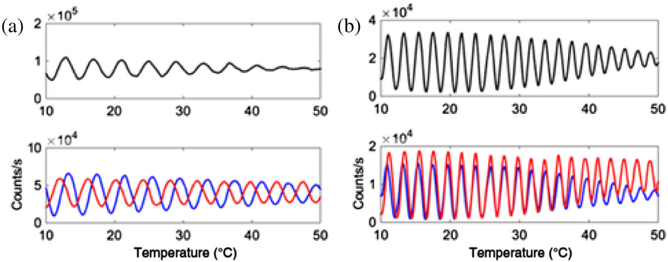
Fig. 6. Interference fringes of the TE (red) and TM (blue) modes versus device temperature scanned from 10°C to 50°C; (a) and (b) correspond to 200 ps and 400 ps, respectively. The top black curve is the sum of the TE and TM modes.
4. IMPLEMENTATION OF ROBUSTNESS AGAINST CHANNEL DISTURBANCE
In the following sections, we will discuss the setup based on our AMZI chips and its polarization-insensitive operation. Considering the gate width limit of the SPD, we select 740 ps delay chips to perform the following experiment. We use the experiment in Fig. 4 to investigate the polarization characteristics of chips for Alice and Bob separately. The interference fringes for Alice and Bob’s chip are shown in Fig. 5(a) and Fig. 7, respectively. We observe that the TE and TM modes are in phase for Alice’s chip in the vicinity of 49°C and for Bob’s chip in the vicinity of 36°C. Despite of the same design of chips, this temperature difference is notable and could be introduced by several factors from the fabrication process, one of which could be that they are made from different silicon wafers.
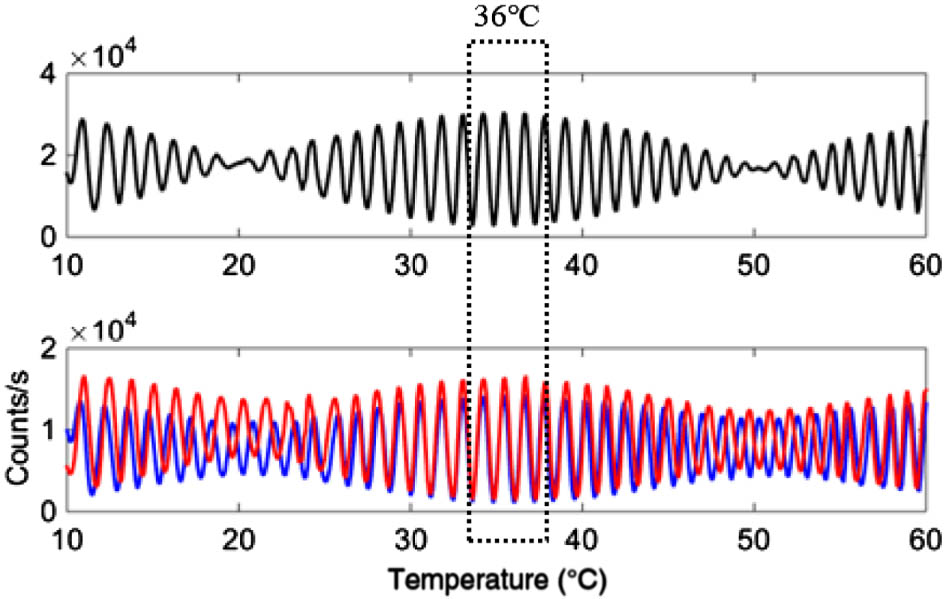
Fig. 7. Interference fringes of the TE (red) and TM (blue) modes versus device temperature, scanned from 10°C to 60°C for Bob’s 740 ps delay AMZI chip. The top black curve is the sum of the TE and TM modes.
Our setup to implement channel polarization insensitivity is demonstrated in Fig. 8, which is implemented by connecting in sequence a pulse laser, a polarization controller (PC), Alice’s AMZI chip, a fiber PBS, a VOA, a polarization scrambler, 20 km SMF, and Bob’s AMZI chip. Each output of Bob’s chip is monitored by an SPD. The PC is used to optimize the polarization linearity degree. The VOA is set to ensure the condition of the single-photon level. The polarization scrambling rate is set to 30 Hz, which is a reasonable estimate to mimic the birefringence variation rate in the field. We input into the system pulses of 50 ps duration at 50 MHz rate, creating three time slots per cycle. Both SPDs are set to count photons at the second time slot, where interference occurs. By scanning the voltage of TOPM2 in Alice’s chip, the output counts are recorded against . The TOPM1s of Alice and Bob’s chips are tuned to balance photon counts between the first and third time slots.
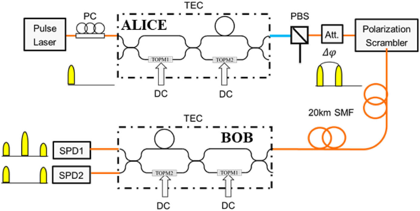
Fig. 8. Experimental setup to prove robustness against polarization disturbance of our interferometers based on silica 740 ps delay AMZI chips.
Since the time delay of 740 ps is much shorter than the variation period (1/30 s) of polarization scrambling, it is quite reasonable to assume that the time-bin photon pair out from Alice experiences identical polarization changes via the polarization scrambler and the 20 km fiber channel. Therefore, the channel birefringence variation causes no change of the modal phase mismatch between the TE and TM modes. If the two modes are in phase for both Alice and Bob, interference with maximum fringe visibility will occur at the system output and be free from the channel polarization disturbance. To ensure that the TE and TM modes are in phase, the device temperature is set to 49°C and 36°C for Alice and Bob, respectively. The PBS works as a filter to further balance the polarization of pulses through the two arms of Alice’s AMZI chip. Therefore, these conditions are sufficient to achieve channel polarization insensitivity; they are equivalent to those stated in Ref. [8].
We scan the of Bob in the vicinity of 36°C at a step of 0.4°C. The fringe visibility is plotted against as shown in Fig. 9. Even if the transmitted light’s polarization is scrambled, we achieve an optimal visibility of 98.72% (with dark counts subtracted), occurring at 36.6°C. The inset graph shows the output interference fringes over 20 km transmission at the optimal device temperature 36.6°C. These results clearly demonstrate that our setup comprising silica PLC-based interferometers is sufficient to implement a channel polarization-insensitive QKD system.
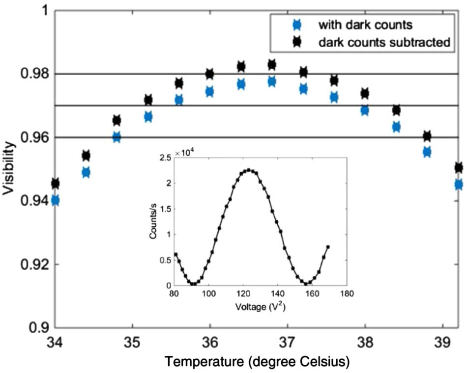
Fig. 9. Fringe visibility versus
Furthermore, we carry on a stability test for our setup. Thanks to lack of superior synchronization techniques in our lab, the 20 km fiber is removed to avoid its adverse effect of long-term length variation. Despite the removal, the results are still reliable for the presence of 30 Hz polarization scrambling. By tuning Alice’s TOPM2, we initially maximize output 1 and minimize output 2 of Bob so that the maximum visibility is observed. Then we maintain the chip temperature with 0.05°C precision and driving voltage of TOPM with 0.05 V precision. The extinction ratio between both outputs is recorded every 5 min over 6 h. Figure 10 shows the plot of the extinction ratio variation over time. The inset shows the interference fringes of both outputs. The extinction ratio of the phase states is between 18 and 21 dB over 6 h, without active phase correction. There are two notable outliers occurring after 5 h, and we will discuss this in the following paragraphs. This result proves the long-term stability of our setup.
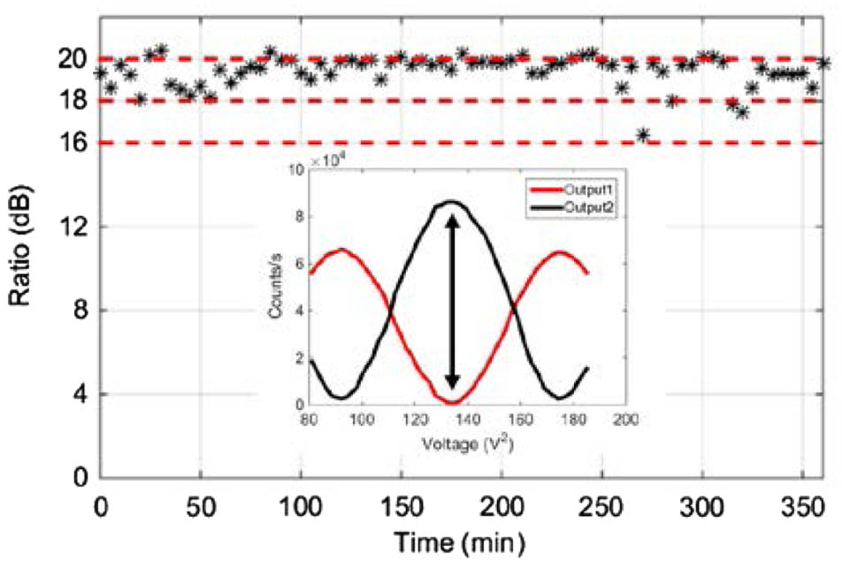
Fig. 10. Proof of long-term stability of our setup. Plot of the extinction ratio between the two outputs from Bob against time over 6 h. The inset shows interference fringes of the two outputs of Bob’s AMZI chip.
Temperature drift has effects on both phase drift and visibility decline. On one hand, temperature drift will cause phase drift in quantum states. For a given amount of temperature drift, the larger the full-wave temperature, the smaller the phase drift. For example, if the temperature control precision is 0.05°C, maximum phase drifts of , , and are expected for 200 ps (4.1°C of full-wave temperature), 400 ps (2.1°C), and 740 ps delay (1.1°C) AMZIs, respectively. On the other hand, temperature drift from the optimal temperature will result in decline of visibility. But the decline is not obvious. According to Fig. 9, when varies between 35°C and 38°C, the visibility stays at more than 97%. This suggests that our chip is able to achieve minor fluctuation of visibility within relatively wide temperature tolerance (3°C). Since a control precision of 0.05°C is much smaller than a tolerance of 3°C, the decline is small.
A comparison of the phase drift caused by device temperature variation and TOPM voltage variation is made. As we can see from the inset graph of Fig. 10, a whole interference fringe ranges from 9.61 to 13.2 V. We can roughly estimate that the phase drift caused by 0.05 V (voltage control precision) is , which is obviously smaller than the phase drift due to 0.05°C temperature drift. Therefore, we conclude that the major cause of the fluctuation is due to temperature variation rather than TOPM. We also estimate from the Fig. 10 inset that a temperature drift of 0.05°C could make the extinction ratio decline to 15 dB, which shows the lower boundary of variations. Actually, we have two outliers between 16 dB and 18 dB, which are within the variation range. In future work we can replace 740 ps with 400 ps or 200 ps AMZI to reduce the phase drift under a given temperature-control precision. Besides, we can work on a more compact packaging to improve the temperature-control precision. Both solutions will increase the long-term stability of phase states.
5. CONCLUSION
We have designed and fabricated 200, 400, and 740 ps delay AMZI PLCs. A novel pulse self-interfering method is proposed to investigate at the single-photon level the polarization characteristics of our AMZI PLCs. The dependency of the AMZI delay on the full-wave temperature is demonstrated. We have demonstrated a setup comprising interferometers based on 740 ps delay AMZI PLCs, which is free from the channel polarization disturbance. Over a 20 km fiber channel with 30 Hz polarization scrambling, our time-bin phase-encoding QKD setup is characterized with an interference fringe visibility of 98.72%. The extinction ratio for phase states is kept between 18 and 21 dB for 6 h without active phase correction. Our setup has presented robustness and long-term stability against the channel disturbance. Silica is a good platform to implement a passive QKD decoder for its low insertion loss, but this should be combined with active phase or intensity modulators such as lithium niobate modulators to realize high-speed state manipulation in QKD systems.
Article Outline
Xiao Li, Meizhen Ren, Jiashun Zhang, Liangliang Wang, Wei Chen, Yue Wang, Xiaojie Yin, Yuanda Wu, Junming An. Interference at the single-photon level based on silica photonics robust against channel disturbance[J]. Photonics Research, 2021, 9(2): 02000222.

