Opto-Electronic Advances, 2018, 1 (6): 180010, Published Online: Mar. 19, 2019
Mode evolution and nanofocusing of grating-coupled surface plasmon polaritons on metallic tip
Figures & Tables
Fig. 1. Geometry of a conical silver tip with grating-assisted light coupling.The excitation light is focused onto the diffractive grating. R is the cross-sectional radius of the tip body gradually decreasing from 1 μm to 20 nm. The tip apex is modeled as a hemisphere with a radius of r .
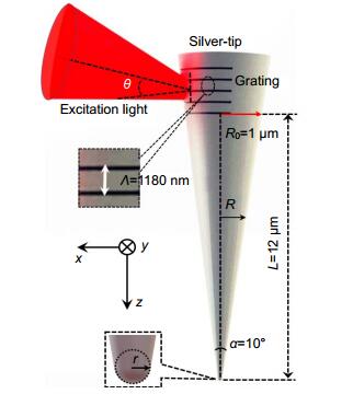
Fig. 2. (a ) Sketch map of SPPs excitation using a planar grating; (b ) Dispersion relationship of SPPs and the grating coupling; (c ) Reflection obtained from the field monitor located above the surface without grating; (d ) Re(H y ) distribution of the grating-coupled SPPs generation and propagation along the silver-air interface with excitation wavelength at λ =632.8 nm and θ =28.5°.

Fig. 3. Effective indices n eff in real part (a ) and imaginary part (b ) of guided SPP modes versus the radius of cylindrical silver guide R . (c ) Sketch map of a silver tip removing the diffracting grating. (d–j ) Transverse modes intensity distributions of guided modes for R =1 μm.

Fig. 4. (a ) Transverse mode intensity distributions of the grating-coupled SPPs at R =1 μm; (b–g ) Transverse mode intensity distributions of the hybrid mode at R =800, 750, 600, 350, 230, and 20 nm, respectively. (h ) Electric field intensity distribution at the tip apex. (i ) Transverse electric field intensity distribution at 1 nm below the tip apex.


Fig. 6. (a ) Gap-mode configuration with the gap distance d =2 nm. (b ) Electric field intensity and polarization distributions in the x-z plane.
(c ) Electric field intensity distribution in the x-y plane at 1 nm below the tip apex. (d ) Comparison of electric field enhancement factor between the non-gap mode (Fig. 4(i) ) and gap mode located at 1 nm below the apex of the silver tip.

Fanfan Lu, Wending Zhang, Ligang Huang, Shuhai Liang, Dong Mao, Feng Gao, Ting Mei, Jianlin Zhao. Mode evolution and nanofocusing of grating-coupled surface plasmon polaritons on metallic tip[J]. Opto-Electronic Advances, 2018, 1(6): 180010.


 PDF全文
PDF全文
