中国激光, 2019, 46 (8): 0802004, 网络出版: 2019-08-13
激光熔注制备ZrO2p热障涂层过程中ZrO2 颗粒的组织演变  下载: 911次
Microstructure Evolution of ZrO2 Particle During Manufacture of ZrO2pThermal Barrier Coating by Laser Melt Injection
图 & 表
图 1. 不同分辨率下原始ZrO2颗粒的形貌。(a)低倍;(b)高倍
Fig. 1. Morphologies of origin ZrO2 particles under different resolution. (a) Low resolution; (b) high resolution
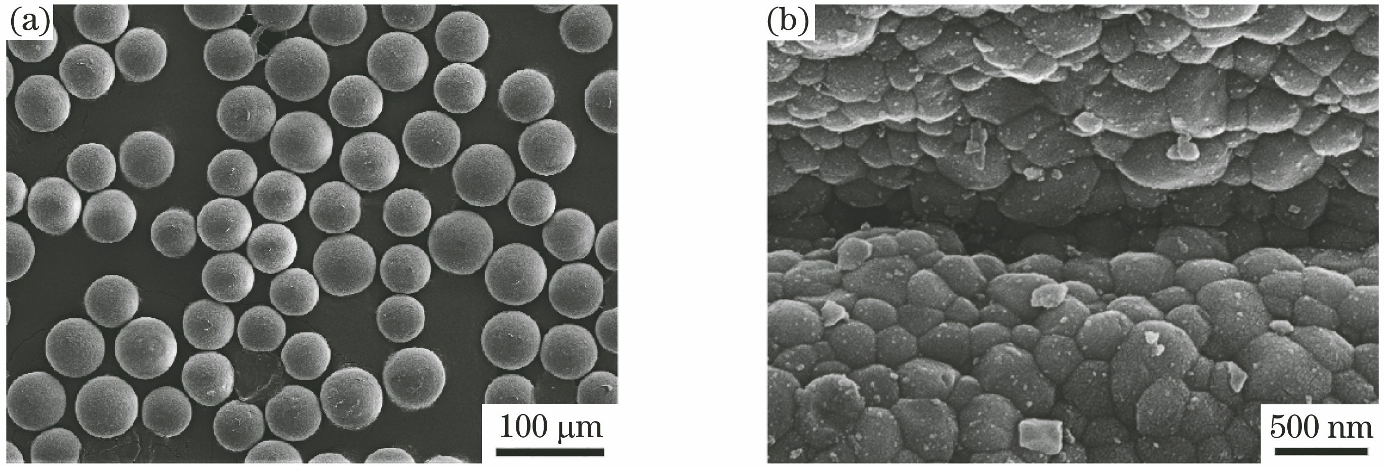

图 3. 热障涂层的横截面形貌。(a)整体形貌;(b)中上部;(c)下部
Fig. 3. Cross-section morphologies of thermal-resistant coating. (a) Overall morphology; (b) upper middle part; (c) lower part

图 4. 激光熔注前后ZrO2颗粒的衍射带衬度图。(a)激光熔注前;(b)激光熔注后
Fig. 4. Diffraction band contrast figures of ZrO2 particle before and after laser melt injection. (a) Before laser melt injection; (b) after laser melt injection

图 5. 热障涂层断口上ZrO2颗粒的微观形貌
Fig. 5. Morphology of ZrO2 particle in fracture of thermal-resistant coating

图 6. XRD图谱。(a)原始ZrO2颗粒;(b)热障涂层
Fig. 6. XRD patterns. (a) Original ZrO2 particle; (b) thermal-resistant coating

图 7. ZrO2相转变。(a)4种相的占比(面积)统计图;(b)原始ZrO2颗粒的相分布图;(c)激光熔注后ZrO2颗粒的相分布图
Fig. 7. Transformation of ZrO2 phases. (a) Statistic chart of fractions (area) of four phases; (b) phase distribution of original ZrO2 particle; (c) phase distribution of ZrO2 particle after LMI

图 8. 热障涂层中ZrO2颗粒的局部放大图。(a)衍射带衬度图;(b)相分布图;(c)取向分布图
Fig. 8. Local zoom map of ZrO2 particle in thermal barrier coating. (a) Diffraction band contrast; (b) phase distribution; (c) orientation distribution


表 1ZrO2颗粒的化学成分
Table1. Chemical composition of ZrO2 particles
|
林守钢, 郭溪溪, 陈浩, 张航, 赖境, 刘德健. 激光熔注制备ZrO2p热障涂层过程中ZrO2 颗粒的组织演变[J]. 中国激光, 2019, 46(8): 0802004. Shougang Lin, Xixi Guo, Hao Chen, Hang Zhang, Jing Lai, Dejian Liu. Microstructure Evolution of ZrO2 Particle During Manufacture of ZrO2pThermal Barrier Coating by Laser Melt Injection[J]. Chinese Journal of Lasers, 2019, 46(8): 0802004.


 PDF全文
PDF全文

