Opto-Electronic Advances, 2019, 2 (1): 180017, Published Online: Mar. 26, 2019
Laser machining of transparent brittle materials: from machining strategies to applications  Download: 750次
Figures & Tables
Fig. 1. Mechanism of laser direct machining transparent brittle materials with long-pulse and ultrashort pulse . (a ) Schematic diagram of long-pulse laser action. (b ) Schematic diagram of ultrashort pulse laser. Figure reprinted with permission from ref.16, Springer-Verlag.
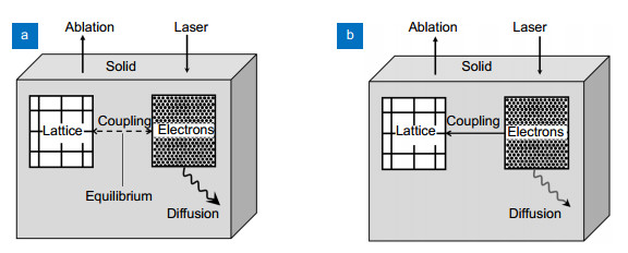
Fig. 2. Laser scribing and breaking . (a ) Laser scribing. (b ) Mechanical breaking. Figure reprinted with permission from ref.17, Springer-Verlag.

Fig. 3. Representation of laser stealth dicing sapphire wafer . (a ) Schematic illustration of the process for slicing. A laser beam is focused on point inside the wafer to form a stealth dicing (SD) layer. (b ) The separation process. Fixing the expanded film with the wafer adhered to the wafer on a two-dimensional platform, and the sapphire wafer is separated by applying an external force. (c) Commonly used multifocal optical system diagram. Figure reproduced from: (a), (b) ref.22, Chinese Journal of Lasers; (c) ref.23.

Fig. 4. (a–d ) The physical process of black color laser patterning of glass substrates. (e ) Black laser pattern of glass substrate. Figure reproduced from: (a)–(d) ref.50, Optical Society of America.

Fig. 5. (a ) Schematic diagram of three-dimensional model. (b ) Temperature variation of different Z positions. Figure reprinted with permission from ref.57, Elsevier Ltd.

Fig. 6. Proposed mechanism of the glass cutting using 1064 nm laser irradiation . (a ) Laser irradiates from the top. (b ) Copper deposition on the underneath of the glass. (c ) The deposited copper absorbs the laser energy and heats up the immediate glass region. (d ) Removal of the molten glass. Figure reprinted with permission from ref.61, Springer-Verlag.

Fig. 7. (a ) Contours of the vapor volume fraction by simulation. (b ) High-speed photography of cavitation bubble. Figure reproduced from ref.64.

Fig. 8. Schematic illustration of the LIBWE process using near-infrared laser pulses with (a) a low repetition rate and (b) a high repetition rate . Figure reprinted with permission from ref.67, Elsevier Ltd.

Fig. 9. (a ) Experimental device for acquiring pressure signals. (b ) The whole acquisition time of the pulse pressure signals. (c ) The part of the pressure signals under single-pulse. Laser energy density of 90.94 J/cm2, solution concentration of 1 mol/L, pulse width of 100 ns, detection distance of 2 mm, laser repetition frequency of 2.5 kHz. Figure reproduced from ref.72.

Fig. 10. Optical micrograph . (a ) Microlens. (b ) Y-shaped microfluidic channel. (c ) The enlarged image of the channel formed by the microlens. Figure reprinted with permission from ref.73, Springer-Verlag.

Fig. 11. (a ) Internal diffraction 1D micro-grating fabricated with fs laser. (b ) Internal diffraction 2D micro-grating fabricated with fs laser. Schemes for (c ) a double-layer 1D micro-grating, and (d ) a stitched double-layer grating. Figure reprinted with permission from ref.74, Springer-Verlag.

Fig. 12. SEM images of details microchannels with reservoir ablated in borosilicate glass . (a ) Channel with reservoir. (b ) Channel. (c ) Close-up of the channel. (d ) Close-up of the bottom of the channel (Ra 100–150 nm). Figure reprinted with permission from ref.75, Springer-Verlag.

Fig. 13. SEM micrograph . (a ) Circle micro-through-hole array. (b ) Triangle micro-through-hole array. (c ) Enlarged image of tip angle of the triangle micro-hrough-hole. Figure reprinted with permission from ref.76, Springer-Verlag, Berlin Heidelberg.

Fig. 14. (a, b ) Shaped cutting parts of sapphire cutting samples. (c ) Tempered glass. (d ) Quartz glass. (e ) Solar glass. Figure reproduced with permission from: (a, b) ref.77, 78. (c–e) ref.79, Applied Laser.

Fig. 15. (a ) SEM micrograph of the line-and-space pattern on fused silica observed at an inclined angle of 45°. (b ) Confocal scanning laser microscopic picture of a grid pattern on fused silica. Figure reprinted with permission from ref.85, Springer-Verlag.

Fig. 16. SEM images of crossed grating patterns on F2 glass fabricated at 248 nm with the two-grating interferometer with double exposure, 250 mJ/cm2 average fluence. First exposure (generating nearly vertical lines): 200 pulses . The number of pulses of the second exposure (nearly horizontal lines) is increasing from (a) to (d). Figure reprinted with permission from ref.91, Springer-Verlag Berlin Heidelberg.

Table1. Comparison of various laser machining methods for transparent brittle materials.
|
Xiaozhu Xie, Caixia Zhou, Xin Wei, Wei Hu, Qinglei Ren. Laser machining of transparent brittle materials: from machining strategies to applications[J]. Opto-Electronic Advances, 2019, 2(1): 180017.


 PDF全文
PDF全文
