激光与光电子学进展, 2018, 55 (1): 011403, 网络出版: 2018-09-10
钛及钛合金激光选区熔化技术的研究进展  下载: 2438次
Research Progress on Technology of Selective Laser Melting of Titanium and Titanium Alloys
图 & 表
图 2. 不同扫描速度下的SLM成形钛构件横截面。 (a) 100 mm·s-1;(b) 200 mm·s-1;(c) 300 mm·s-1;(d) 400 mm·Fig. 2. Cross-sectional images of Ti components formed by SLM under different scanning speeds. (a) 100 mm·s-1; (b) 200 mm·s-1; (c) 300 mm·s-1; (d) 400 mm·
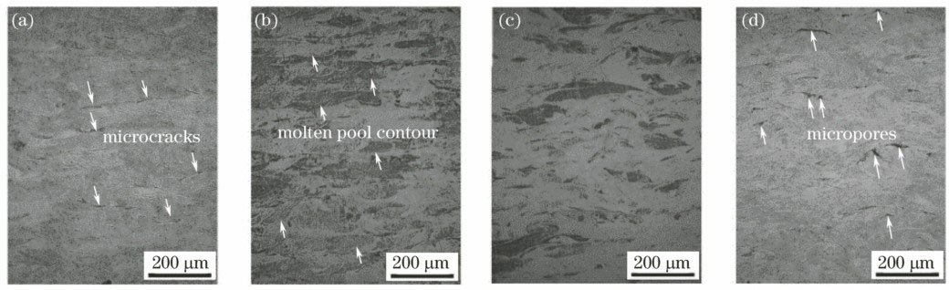
Fig. 2. Cross-sectional images of Ti components formed by SLM under different scanning speeds. (a) 100 mm·s-1; (b) 200 mm·s-1; (c) 300 mm·s-1; (d) 400 mm·
图 3. 不同衍射角下的 SLM钛构件的XRD谱。(a) 2θ=38.45°;(b) 2θ=40.18°[28]
Fig. 3. XRD spectra of Ti components formed by SLM under different diffraction angles. (a) 2θ=38.45°; (b) 2θ=40.18°[28]

图 4. 不同扫描速度下的SLM成形钛构件显微结构。(a) 100 mm·s-1;(b) 200 mm·s-1;(c) 300 mm·s-1;(d) 400 mm·Fig. 4. Microstructures of Ti components formed by SLM under different scanning speeds. (a) 100 mm·s-1; (b) 200 mm·s-1; (c) 300 mm·s-1; (d) 400 mm·
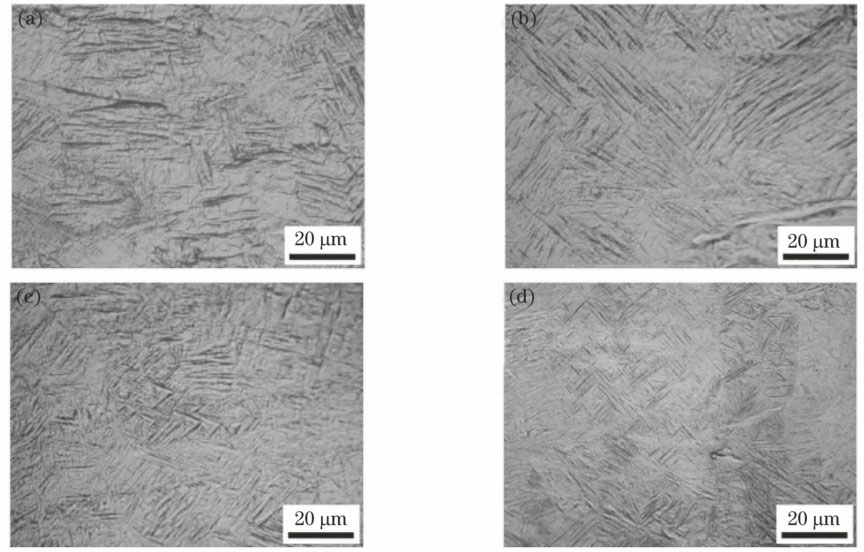
Fig. 4. Microstructures of Ti components formed by SLM under different scanning speeds. (a) 100 mm·s-1; (b) 200 mm·s-1; (c) 300 mm·s-1; (d) 400 mm·
图 5. (a)(b)无SMF和(c)(d)有SMF下的CP-Ti的SLM样品显微结构
Fig. 5. Microstructures of CP-Ti samples formed by SLM (a)(b) without and (c)(d) with SMF
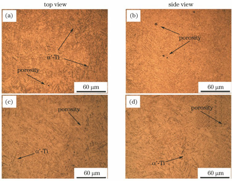
图 6. 不同条件下的断口截面的(a)(b)光学显微图、(c)(d)扫描电镜图、(e)(f)取向图和(g)(h)反极图[31]
Fig. 6. (a)(b) Optical microscopy images, (c)(d)scanning electron microscopy images, (e)(f) orientation maps and (g)(h) inverse pole figures of fracture section under different conditions[31]

图 7. Ti6Al4V粉末形貌。(a) 500×;(b) 3000×
Fig. 7. Morphologies of Ti6Al4V powder. (a) 500×; (b) 3000×
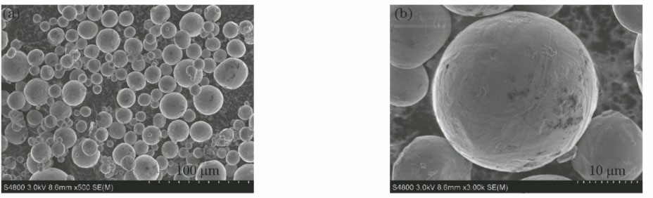
图 8. 不同激光扫描速度下的熔化凝固过程[43]。(a) 5 mm·s-1;(b)10 mm·s-1; (c) 25 mm·s-1;(d) 50 mm·s-1;(e) 100 mm·s-1
Fig. 8. Melting and solidification processes under different laser scanning speeds[43]. (a) 5 mm·s-1; (b) 10 mm·s-1; (c) 25 mm·s-1; (d) 50 mm·s-1; (e) 100 mm·s-1

图 9. 扫描策略对显微结构的影响[53]。(a)(b)(c)(d)单向扫描;(e)(f)(g)(h)交叉扫描
Fig. 9. Influence of scanning strategy on microstructures[53]. (a)(b)(c)(d) Unidirectional scanning; (e)(f)(g)(h) cross scanning

图 10. 激光能量输入为(a) 0.5E0、(b) E0、(c) 2E0时,Ti6Al4V的SLM成形样件显微结构[54]
Fig. 10. Microstructures of Ti6Al4V specimens formed by SLM with laser energy input of (a) 0.5E0, (b) E0 and (c) 2
图 11. (a)支撑结构示意图;(b) As/Ap=0.25时的支撑结构图[63]
Fig. 11. (a) Schematic of support structure; (b) schematic of support structure with As/Ap=0.25[63]

图 12. Ti6Al4V 的SLM成形构件的显微结构[63]。(a) As/Ap=0.125;(b) As/Ap=0.25;(c) As/Ap=0.4;(d) As/Ap=1
Fig. 12. Microstructures of Ti6Al4V components formed by SLM [63]. (a) As/Ap=0.125; (b) As/Ap=0.25; (c) As/Ap=0.4; (d) As/Ap=1

图 13. SLM制备的结构件。(a) CP-Ti;(b) TiTa
Fig. 13. Structural components fabricated by SLM. (a) CP-Ti; (b) TiTa
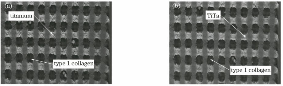
图 14. (a) 表面处理后的个性化骨板;(b) 骨板和骨盆模型的匹配
Fig. 14. (a) Individual bone plate after surface treatment; (b) matching between bone plate and pelvic model
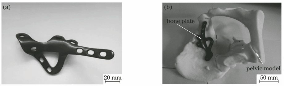
图 15. 梯度融合器的(a)成形件和(b)模型
Fig. 15. (a) Formed part and (b) model of gradient fusion cage section
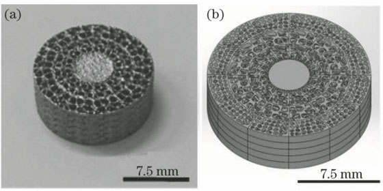
图 16. SLM成形制备的Ti6Al4V吸声器。(a)样品A;(b)样品B
Fig. 16. Ti6Al4V sound absorbers fabricated by SLM. (a) Sample A; (b) sample B
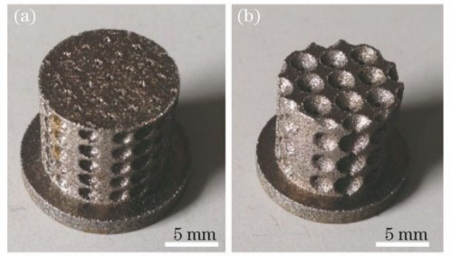
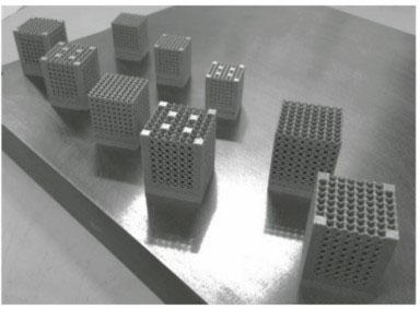
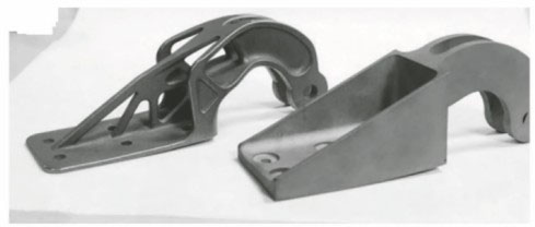
表 1不同SLM成形设备所得的CP-Ti的力学性能
Table1. Mechanical properties of CP-Ti fabricated by different SLM equipments
|
表 2不同加工条件下Ti6Al4V的SLM成形构件的力学性能
Table2. Mechanical properties of Ti6Al4V components formed by SLM under different process conditions
|
李俊峰, 魏正英, 卢秉恒. 钛及钛合金激光选区熔化技术的研究进展[J]. 激光与光电子学进展, 2018, 55(1): 011403. Li Junfeng, Wei Zhengying, Lu Bingheng. Research Progress on Technology of Selective Laser Melting of Titanium and Titanium Alloys[J]. Laser & Optoelectronics Progress, 2018, 55(1): 011403.


 PDF全文
PDF全文

