Chinese Optics Letters, 2016, 14 (10): 102302, Published Online: Aug. 2, 2018  

Charge distribution into illuminated dye-doped surface stabilized ferroelectric liquid crystal cell Download: 836次

Author Affiliations
1 Institute of Microelectronics and Optoelectronics, Warsaw University of Technology, Warsaw 00-665, Poland
2 Institute of Applied Physics, Military University of Technology, Warsaw 00-908, Poland
Abstract
Surface stabilized (anti) ferroelectric liquid crystal cells can be used as an optically addressed media for optical data processing. The structure of the cell has to contain a photo sensible agent, i.e., an absorbing dye-doped orienting layer. The all-optical generation of the diffractive grating can be done due to the switching parameters of the smectic slab within cells with a sensitive layer. This Letter considers a study of the optically induced charge generation into the dye-doped layer, and the explanation of the phenomena of the selective molecular director reorientation, while cell driving what leads to the induction of phase grating.

The mechanisms of the switching of the surface stabilized antiferroelectric liquid crystal (SSAFLC) structure[1] and surface stabilized ferroelectric liquid crystal (SSFLC) structure[2] driven by an optically induced effective electric field Eeff were discussed before. In Refs. [1,2], the photo- and electro-optical properties of the synclinic SmC* and anticlinic SmCA* structures were examined and presented. Various operating modes of studied structures have been shown and described already. In this Letter, the mechanism of the optically driven switching of the smectic surface stabilized structure is proposed and discussed in reference to the optical addressing of the cells.

Opposite to the SSAFLC, which exhibits three-state switching, the SSFLC can adopt only two optical states, see Fig. 1[3].

Fig. 1. Molecular director at the SSFLC can adopt two synclinic structures where the tilt angle θ is defined by an angle between the n⃗ and k⃗ versors. These states are metastable and can exist without any external electric fields as a result of the minimum energy condition for the SSFLC structure at particular boundary conditions. These states [(a) and (b)] are characterized by the different orientation of the optical axes; polarized light passing through the SSFLC can be modulated by switching between these states. When the external field reaches +Esat, the SSFLC layer will be fully switched to the state shown in (b), and the application of the negative field of value Esat drives the liquid crystal (LC) layer to the state shown in (a).

下载图片 查看所有图片

In Fig. 1(a), the assumed initial state of the SSFLC structure is shown. This state is induced by anchoring of the molecular director n⃗ of the synclinic layered smectic structure on the surface of the orienting. The SSFLC structure remains stable at this state without any external field (in this case electric)[48" target="_self" style="display: inline;">8]. In general, the SSFLC structure is optically positive and uniaxial with an effective optical axis collinear with the molecular director n⃗ (with the extraordinary refractive index ne associated) at the angle θ (tilt) off the normal smectic layer (given by the versor k⃗), which is simultaneously parallel to the boundary planes. When the SSFLC structure is affected by an electric field E⃗ (where E⃗ is perpendicular to the plane defined by the versors n⃗ and k⃗) with the value overcoming a material specific threshold level E>Eth, the director n⃗ switches to the other state, where again E⃗ is perpendicular to the plane defined by the versors n⃗ and k⃗ (Fig. 1(b)). The movement of the director n⃗ is initialized by the interaction of the electric field E⃗ with the spontaneous polarization Ps via force momentum M⃗=E⃗×Ps. The inverse switch can be done by the electric field applied to the value of E⃗ of the magnitude E<Eth. Such an in-plane switching of the optical axis accompanied with the memory effect can be widely utilized in display and photonic applications. One of these is the preparation of switchable diffractive optical elements.

Although the standard applications of SSFLC structures demand driving by an electric field, the alternative solutions are possible[2,915" target="_self" style="display: inline;">15]. Here, an optically induced in-plane switching of an SSFLC structure is presented by the implementation of a photosensitive orienting (POR) layer. Using a space separated illumination of a POR, separated fields of charges are induced. Thus, a pattern-like illumination can take effect in the patterned charge distribution in the POR layer. It was previously demonstrated[1,2,9] that a photo induced charge affects an effective electric field (Eeff), driving the liquid crystal (LC) structure inside the cell volume.

When the superposition of the external electric field (EU) and the electric field caused by illumination (Eilum) is greater than switching threshold level (Eth), it can locally induce the LC molecules to switch from the initial to the opposite synclinic state. Using a periodic mask shielding an illuminated area with an SSFLC structure, a phenomenon of optical recording of the phase grating can be observed. Similar effects can be done by an optical interference pattern in a plane of the POR layer. The general scheme of an optical generation of the micro interferograms onto the SSFLC layer is shown in Fig. 2.

Fig. 2. (a) Creation of the interference gratings onto the SSFLC slab. Initial state of the LC layer in the cell with one of the orienting layer doped by dye (POR). (b) I1 and I2 are the interfering laser beams, The interference pattern consists of neighboring areas with a minimum and maximum intensity of the illumination (Imax and Imin, respectively), the green line is for show purposes only and roughly denotes a border between these areas. The illumination locally affects the effective electric field (Eeff) that is superposed with the applied electric field (Eu) which exceeds the threshold level (Eth) and drives the director n⃗ locally to an opposite state. (c) The reading laser beam illuminates the SSFLC slab uniformly and when the reading beam intensity (Iread), hence Eillum, is superposed with Eu does not reach the Eth level, the grating should be ready for optical reconstruction.

下载图片 查看所有图片

Fig. 3. LC cell with the POR prepared as a mixture of the basic solution (nylon 6/6) and dye-dopant (explanation in text).

下载图片 查看所有图片

The cell has a standard construction with one of the polyimide orienting layers replaced by dye-doped one (POR), shown in Fig. 3[16].

The cells were prepared using polished soda lime float glass substrates (thickness d=0.7mm) covered subsequently with a SiO2 ion blocking layer and a conductive, transparent indium tin oxide (ITO) layer of the proper resistivity R=100Ω/sq. The orienting layers of a thickness of 60 nm were deposited on the substrates by spin coating, using two kinds of solutions of the commercial polyamide nylon 6/6 (Fluka) in 2,2,2-trifluoroethanol, where both solutions were contaminated by 0.05% by a dry weight of nylon 6/6. The solutions were prepared in a few hours by the steering of the 2,2,2-trifluoroethanol with the nylon 6/6 balls to completely dissolve the polyamide. The final solution was filtrated using a nanofilter. Afterward, the solution was treated by ultrasonic agitation for 1 h at an elevated temperature.

The POR was obtained with the surface spin coating of the substrate with the mixture of the basic solution (nylon 6/6) doped with the anthraquinone dye (blue 2590, with a maximum absorption of λ2590650nm). The dye-doped solution was prepared in two steps: the 2590 anthraquinone dye was added to the basic nylon 6/6 solution in an amount necessary to obtain a saturated solution at room temperature. The basic solution and dye-doped saturated ones were mixed in a proportion of 101 for obtaining a final dye-doped surface agent. Such a concentration of the dye was observed to be an optimal one, the means were most effective while simultaneously not damaging the orienting properties of the nylon 6/6 layer.

Substrate glasses spin coated with basic and dye-doped surface agents were dried and uniformly rubbed according to the standard procedure. The ready-made POR layer thickness was between 85 and 130 nm, according to the measurements done with the use of the ellipsometric method (UV-VIS-IR spectroscopic ellipsometer SE850 by Sentech). Cells with a single photosensitive layer were assembled using one glass substrate with a basic nylon orienting layer and the other with a dye-doped nylon 6/6 one (POR). Both substrates forming a measuring cell were treated with antiparallel rubbing at a controlled regime. To avoid the induction of a two domain structure, an extra cross-rubbing has been applied to the surface of a pure nylon 6/6 orienting layer, according to a custom procedure elaborated at several “try and check” tests. The cells were assembled using spherical glass spacers of a diameter of d=1.6μm, deposited on the surfaces by a wet spraying method, and then by making an adhesive glue seal made by screen printing.

The cells have been filled by capillary action with a smectogenic mixture W212-2E at the isotropic state within the vacuum chamber. The mixture of W212-2E used was prepared at the Institute of Chemistry MUT. The uniform orientation of the SSFLC structure was obtained during the slow cooling (0.05K/min) from the isotropic state at the vicinity of the low frequency electric field (f=15Hz, Upp=1.5V).

The optical uniformity of the LC structure was checked using of Biolar PI polarizing microscope at room temperature (see Fig. 4). The SSFLC structure was inspected in a standard birefractive setup for electro-optical measurements. At room temperature, it has a tilt angle of Θ37°, a spontaneous polarization of Ps240nC/cm2, and a switching time of τ1090350μs. The electro-optical response of the test cell is shown in Fig. 5.

Fig. 4. Photomicrograph of the SSFLC cell with the POR filled with W212-2E ferroelectric LC observed under the polarizing microscope BIOLAR PI (by PZO Poland) within the birefractive setup. The cross denotes the polarizer and analyzer orientation. (a) Left area is the view of the SSFLC between the ITO electrodes while the E+ electric field is applied. (b) The same cell while the E electric field is applied.

下载图片 查看所有图片

Fig. 5. Electro-optical response of the cell with SSFLC structure (W212-2E mixture) with the orienting layer (nylon 6/6) and the POR (Nylon 6/6 + dye—blue 2590). Measurements were performed for Upp=8V, f=1Hz, and t=25°C. The cell shows a W-shaped behavior.

下载图片 查看所有图片

The aim of the study was to observe the influence of illumination on the switching process inside the SSFLC structure and the registration of the light generated charge and its distribution. The last one phenomenon is one of the most important at the generation of the phase grating and optical pattern recording within the SSFLC cells[1]. Since a current flow within the cell is proportional to a charge existing and moving through the cell, the last one can be measured by the observation of the current at the time domain. The assumption is that the cell with a photosensitive POR layer can be treated as a complex capacitor with two plate electrodes (ITO and ITO + POR) and dielectric material in between (LC layer), see Fig. 6. Regarding this assumption, we can further describe the optical pattern recording.
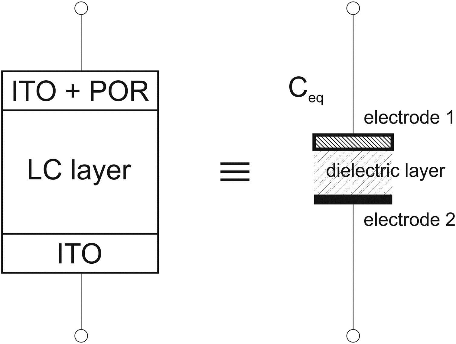
Fig. 6. Equivalent electrical circuit of the photosensitive cell. For clarity, the influence of the electrical properties of the electrical wires and assembled cell (including aligning layers) were omitted and treated as a constant in reference to the assumed conditions.

下载图片 查看所有图片

In the conventional way, the SSFLC structure can be switched as an effect of applied voltage connected to the capacitor’s electrodes. In this case, both plate electrodes can be treated as plates with identical but opposite charges [see Fig. 7(a)]. Thus, the electric field in between can be written as the basic formula Eeff=E++E=σ2ε0εr+σ2ε0εr,where E+, E is the electric field generated at the electrodes generated by applied voltage, and σ is the charge density caused by the electric field.
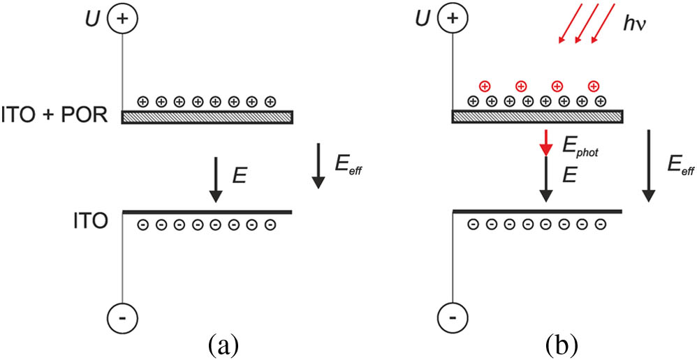
Fig. 7. Charge analysis in the complex capacitor with voltage applied; cases without and with the illuminating photon beam are shown as (a) and (b), respectively.

下载图片 查看所有图片

Within an illuminated cell some additional charges are generated (photo induced carriers) in the photosensitive layer; thus, there exists two different charge densities (σ, σphot), and this affects the effective electric field Eeff inside this complex capacitor (refer to Fig. 2). In this case, the charge existing on the plate electrodes just after the illuminating beam interacts with the POR can be schematically described, as shown in Fig. 7(b), and the formula changes as follows: Eeff=E+phot+E=σphot2ε0εr+σ2ε0εr,where σphot is the photonic charge density, the result of the superposition of the electrically and optically induced charges.

As a consequence, the current flow increases when the cell is illuminated with the photon beam fitted to the absorption bandwidth of the dye used in the POR. Experimental measurements should confirm these assumptions.

The examined SSFLC cell (with the W212-2E mixture) under study was connected to a sensitive electrometer (Keithley 617) and initially polarized with use of a high impedance output of the waveform generator (Agilent 33220A). All the measurements were done in a remote mode by a dedicated application, working under the NI LabView environment. The schematic diagram of the measurement setup is shown in Fig. 8. The setup was tested and calibrated for the real-time observations of a current flow Iflow at the level of pA. Due to the very sensitive measurements of the current in a setup of all electric connections, the LC cell has been carefully shielded by the ground.
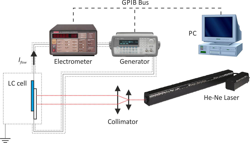
Fig. 8. Measuring setup. A collimated laser beam is applied as an option. All wires and an LC cell under investigation were very precisely shielded by the ground.

下载图片 查看所有图片

The initial measurements were performed on the cell without illumination and no electric polarization. The curve shown in Fig. 9. proves that the LC cell can be treated as a real capacitor a with very large equivalent series resistance (ESR) with a large time constant. As shown, the current flow is still dynamically changing even after a period of approximately 80 s. It can be estimated that a time constant τ of the equivalent RC circuit is a quarter of the shown period that means τ20s.
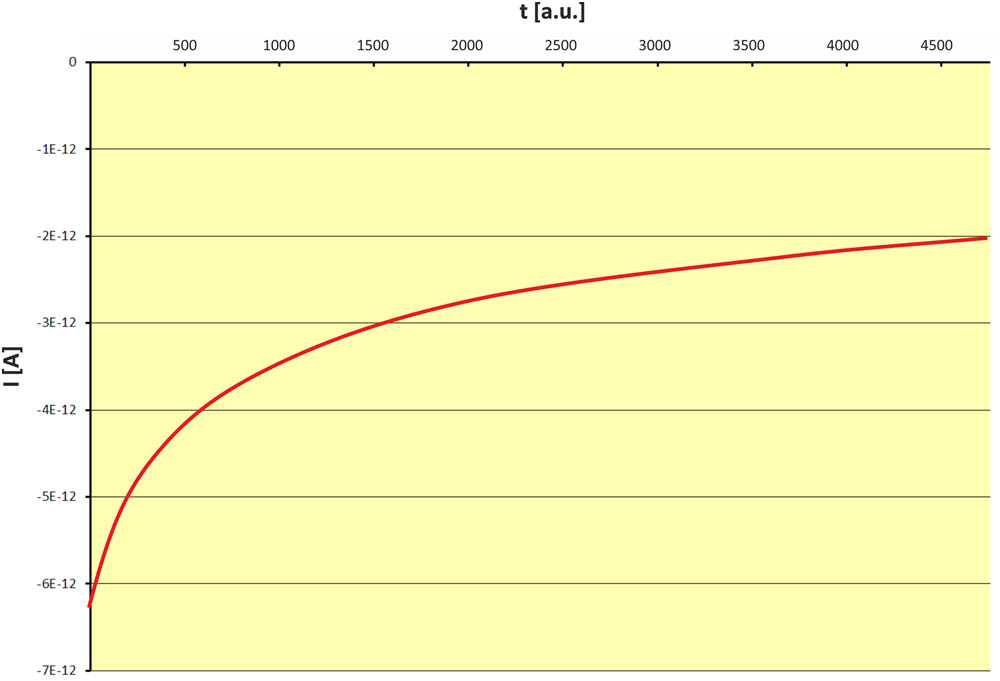
Fig. 9. Current flow through the SSFLC structure without the polarizing voltage applied (U=0V) in darkness. The smoothened curve represents measurements points collected every 0.36 s (1a.u.=0.36s).

下载图片 查看所有图片

The next step was to determine of a value of the polarizing voltage Uopt to achieve a possible maximum difference in current flow between the illuminated and non-illuminated cell. To do this, the LC cell was polarized with different voltages (from 1.2 to 5 V with a step of 0.1 V), and a current flow of the cell was measured when the laser beam (uniform illumination) was switched. In Fig. 10, the absolute differences between the current flowing through the cell at two states are presented, where the illumination of the cell was switched on or off (“dark–>illum” and “illum–>dark,” respectively). It can be seen that the response of the cell has a kind of saturation of the electro-optical response and it starts from approximately U22.4V. Then in consecutive experiments, the SSFLC structure worked under the voltage U2V.
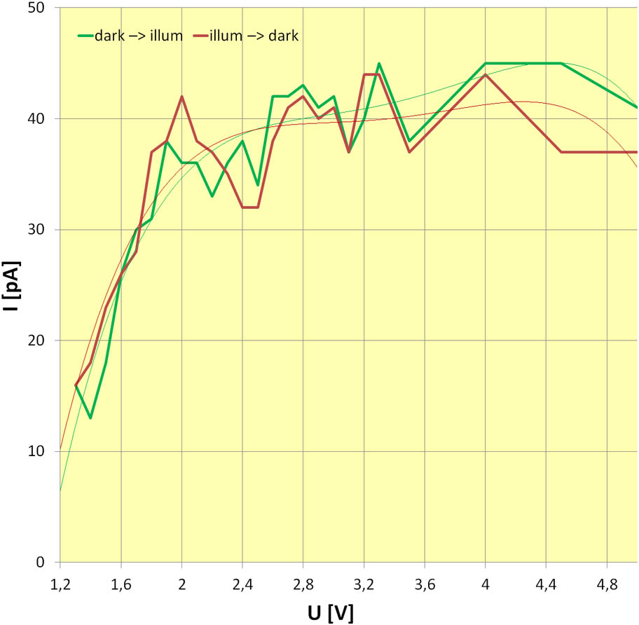
Fig. 10. Electro-optical response of the SSFLC structure in a function of the polarizing voltage; the current measurements and results represent the absolute difference between the current flow when the illumination of the cell was switched on or off (“dark–>illum” and “illum–>dark,” respectively). At the level of U22.4V, a kind of saturation of the observed effect is present (showed by trend lines).

下载图片 查看所有图片

Measurements of the LC cell response under illumination was done for a laser beam power density of approximately P2mW/mm2 (He-Ne laser with P=35mW, diameter of the collimated beam d5mm). Analyzing the results, ton and toff for the SSFLC structure for the optical drive can be estimated. These are estimated, respectively, as 8.6 and 6.8 s (shown on Fig. 11). The increase of the flowing current proves that the assumptions regarding the existance of photo induced charges in the POR is correct.
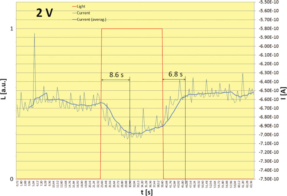
Fig. 11. Measurement of the current flow as an LC cell response for illumination. Measurements were done when U=2V was applied to the cell.

下载图片 查看所有图片

To conclude, it can be listed as follows: The current flow in an SSFLC (as for the W212-2E mixture) structure is very low and can be estimated at the level of tens of pA to a few of nA. This changes with cell thickness, mixture purity, quality of the ITO electrodes, etc.The cell response for optical driving is a polarizing voltage dependent and has a kind of saturation effect over U2V. The molecular director needs a few seconds for switching when the SSFLC structure within a cell with a POR layer is illuminated with a laser beam, and is a bit shorter to switch back when the illumination is cut off. On other hand, the first response visible on the current flow when illumination is applied appears during the very first measurement point after the beam is turned on (it is faster than 360 ms, which is the limiting measurement repeatability of the used hardware).The experimental results reveal that the discussed model of the cell is correct in general, the cell with the POR layer has similar electrical properties as a complex capacitor with parallel plane electrodes, which can generate additional charges when illuminated.However, the optically induced local switching of the SSFLC structure can be realized; the results show that this effect is gentle and has to be very carefully tuned for each of the applied cells.

References

[1] SutkowskiM.PiecekW.GrudniewskiT.ParkaJ.Nowinowski-KruszelnickiE., Opt. Lasers Eng.49, 1330 (2011).

[2] SutkowskiM.GrudniewskiT.PiecekW.MorawiakP.ParkaJ.Nowinowski-KruszelnickiE.RaszewskiZ., Mol. Cryst. Liq. Cryst.502, 195 (2009).

[3] LagerwallS. T., Ferroelectric and Antiferroelectric Liquid Crystals (Wiley, 1999).

[4] DozovI., SID Symp. Dig. Tech. Pap.34, 946 (2003).DTPSDS0097-966X

[5] PozhidaevE.ChigrinovV., Crystallogr. Rep.51, 1030 (2006).CYSTE31063-7745

[6] RaszewskiZ.SunX. W.PerkowskiP.PiecekW.ZielinskiJ.DabrowskiR.Nowinowski-KruszelnickiE.KedzierskiJ., in Asia Optical Fiber Communication and Optoelectronic Exposition and Conference, OSA Technical Digest (CD) (2008), paper SuJ3.

[7] TalaricoM.GolemmeA., Mol. Cryst. Liq. Cryst.465, 341 (2007).

[8] WahlJ.JainS. C., Ferroelectrics59, 161 (1984).FEROA80015-0193

[9] SutkowskiM.GrudniewskiT.ZmijanR.ParkaJ.Nowinowski-KruszelnickiE., Opto-electron. Rev.14, 335 (2006).OELREM1230-3402

[10] RudquistP.ElfströmD.LagerwallS. T.DabrowskiR., Ferroelectrics344, 177 (2006).FEROA80015-0193

[11] SutkowskiM.GrudniewskiT.ParkaJ.MiniewiczA., Proc. SPIE4759, 445 (2002).PSISDG0277-786X

[12] StrackeA.WendorffJ. H.GoldmannD.JanietzD., Liq. Cryst.27, 1049 (2000).LICRE60267-8292

[13] KahnF. J., Appl. Phys. Lett.22, 111 (1973).APPLAB0003-6951

[14] MaoC. C.JohnsonK. M.ModdeG., Ferroelectrics114, 45 (1991).FEROA80015-0193

[15] ZhuangS.QiuY.JiangY.TuY.ChenW. M., Proc SPIE1558, 149 (1991).

[16] ClarkN. A.LagerwallS. T., Appl. Phys. Lett.36, 899 (1980).APPLAB0003-6951

Marek Sutkowski, Wiktor Piecek. Charge distribution into illuminated dye-doped surface stabilized ferroelectric liquid crystal cell[J]. Chinese Optics Letters, 2016, 14(10): 102302.


引用该论文: TXT   |   EndNote

相关论文

加载中...

关于本站 Cookie 的使用提示

中国光学期刊网使用基于 cookie 的技术来更好地为您提供各项服务,点击此处了解我们的隐私策略。 如您需继续使用本网站,请您授权我们使用本地 cookie 来保存部分信息。
全站搜索
您最值得信赖的光电行业旗舰网络服务平台!