16 nm极紫外光刻物镜热变形对成像性能影响的研究  下载: 1348次
Effect of Thermal Deformation on Imaging Performance for 16 nm Extreme Ultraviolet Lithography Objective
1 北京理工大学光电学院光电成像技术与系统教育部重点实验室, 北京 100081
2 北京航天计量测试技术研究所, 北京 100076
图 & 表
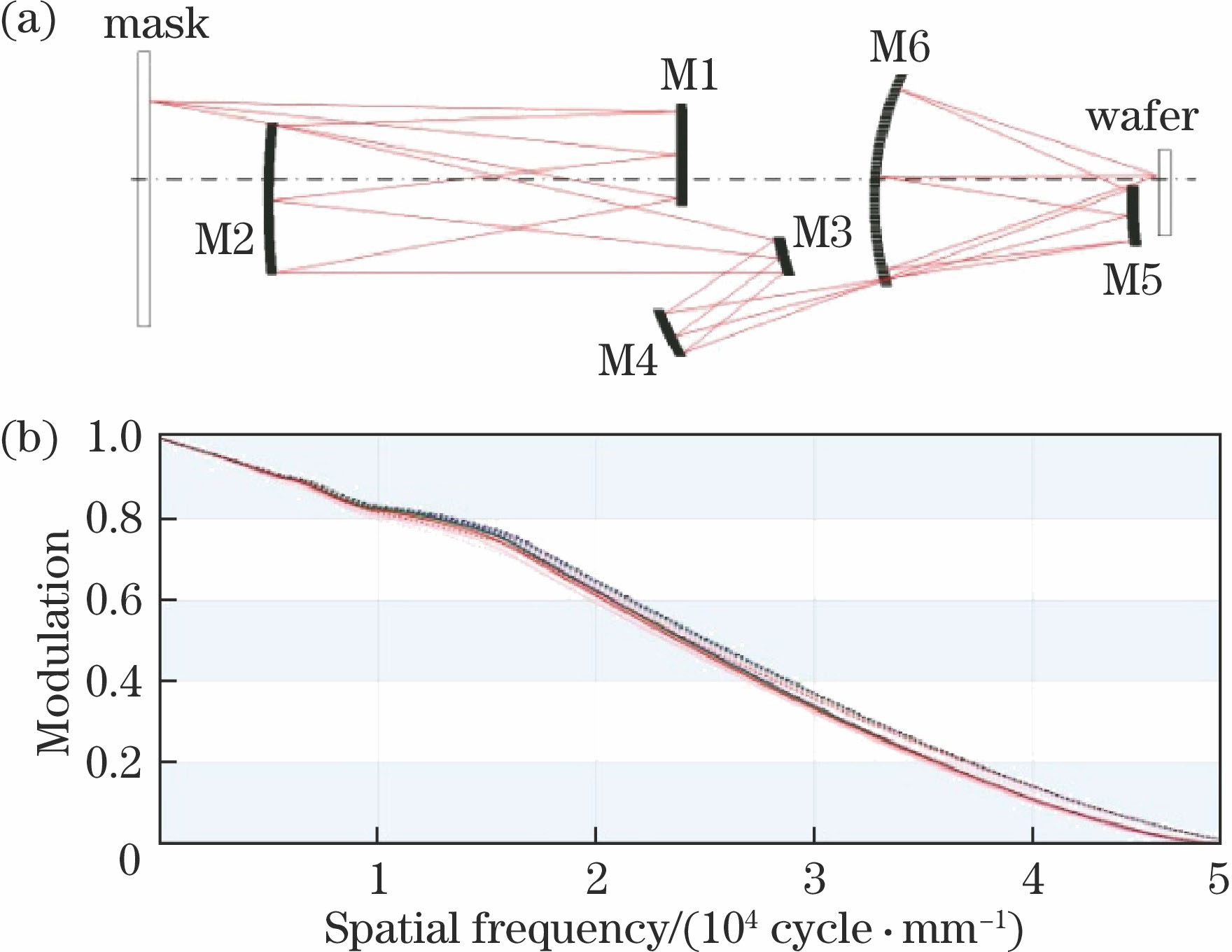
图 1. (a) EUVL物镜光路图;(b) MTF
Fig. 1. (a) Layout of EUVL objective; (b) modulation transfer function
下载图片 查看原文
图 2. M1反射镜的有限元模型
Fig. 2. Finite element model of M1 mirror
下载图片 查看原文
图 3. 反射镜热加载-时间图
Fig. 3. Heat loading steps-time plot of mirror
下载图片 查看原文
图 4. (a)环形照明光瞳的光强分布;(b)掩模面上的照度分布
Fig. 4. (a) Annular distribution of luminous intensity; (b) distribution of illuminance on mask
下载图片 查看原文
图 5. Mo/Si多层膜反射率相对入射角的变化曲线
Fig. 5. Curve of reflectivity of Mo/Si multilayer relative to incidence angle
下载图片 查看原文
图 6. M1反射镜最后仿真时刻的(a)温度分布图和(b)热变形分布图
Fig. 6. (a) Temperature and (b) thermal deformation maps of M1 mirror at the end of last-heat-loading step
下载图片 查看原文
图 7. 各反射镜的(a)温度和(b)热变形RMS随时间的变化曲线
Fig. 7. Curves of (a) temperature and (b) thermal deformation RMS value of each mirror relative to time
下载图片 查看原文
图 8. 像方环形视场
Fig. 8. Image annular field of view
下载图片 查看原文
图 9. 高低温态时刻物镜系统的(a)波像差RMS和(b)畸变
Fig. 9. (a) WFE RMS and (b) distortion of objective system on the moments of maximum temperature and minimal temperature
下载图片 查看原文
图 10. 各高温态反射镜热变形引起的边缘视场的(a)波像差RMS和(b)畸变
Fig. 10. (a) WFE RMS and (b) distortion of edge image field of view caused by thermal deformation of each mirror on maximum temperature moment
下载图片 查看原文
图 11. 各反射镜曲率、主光线投射高度和入射角
Fig. 11. Curvature of each mirror, height of chief ray and incidence angle of chief ray
下载图片 查看原文
表 1反射镜及支撑结构材料的特性参数
Table1. Characteristic parameters of mirrors and supporting mount materials
| Parameter | ULE | Si | Mo | Invar |
|---|
| Density /(g·cm-3) | 2.205 | 2.33 | 10.3 | 8.12 | | Thermal conductivity /(mW·mm-1·K-1) | 1.31 | 148 | 138 | 1.09 | | Specific heat /(J·kg-1·K-1) | 0.766 | 0.712 | 0.255 | - | | Emissivity | 0.735 | 0.122 | 0.122 | 0.28 | | Young's ratio /GPa | 67.6 | 107 | 272 | 134 | | Poisson's ratio | 0.17 | 0.25 | 0.25 | 0.3 | | Thermal expansion coefficient /(10-6 K-1) | 0.02 | 2.50 | 5.35 | 1.06 |
|
查看原文
表 216 nm产业化EUVL样机产率模型
Table2. Model of 16 nm EUVL prototype productivity
| Item | Value |
|---|
| Throughout /(wafer·h-1) | 125 | | EUV power of intensity focus /W | 250 | | Total time for one wafer /s | 28.8 | | Exposure time /s | 7.2 | | Wafer exchange time /s | 721.6 | | Wafer diameter /mm | 300 | | Resist sensitivity /(mJ·cm-2) | 15 | | Power at wafer /mW | 689 |
|
查看原文
表 3各反射镜吸收极紫外光能量密度相关计算数据
Table3. Relevant calculating data of the absorbed EUV power density for each mirror
| Mirror | M1 | M2 | M3 | M4 | M5 | M6 |
|---|
| Mean incidence angle /(°) | 6.3 | 6.6 | 22.4 | 11.5 | 12.4 | 4.7 | | Mean reflectivity /% | 67.5 | 67.7 | 67.3 | 67.6 | 67.7 | 67.5 | | Absorbed EUV power /mW | 2402.19 | 1609.03 | 1102.80 | 735.38 | 495.58 | 337.59 | | Reflective area /mm2 | 17439 | 33338 | 4782 | 12508 | 5077.4 | 55102 | | Absorbed power density /(mW·mm-2) | 0.138 | 0.048 | 0.231 | 0.059 | 0.098 | 0.006 |
|
查看原文
表 4物镜成像性能要求
Table4. Imaging performance demands for objective
| Item | Value |
|---|
| WFE RMS | <0.03λ | | Distortion | <1.1 nm |
|
查看原文
表 516 nm与22 nm EUVL物镜的热变形分析结果
Table5. Analysis of thermal deformation for 16 nm and 22 nm EUVL objectives
| Item | PO1 | PO2 |
|---|
| 3D thermal deformation (M1-M6) /nm | 8.3,3.8,6.2,1.1,4.2,0.5 | 1.6,4.1,4.8,0.4,2.5,0.2 | | WFE RMS /λ | 0.1 | 0.006 | | Maximum distortion /nm | 56 | 7 |
|
查看原文
李艳秋, 刘岩, 刘丽辉. 16 nm极紫外光刻物镜热变形对成像性能影响的研究[J]. 光学学报, 2019, 39(1): 0122001. Yanqiu Li, Yan Liu, Lihui Liu. Effect of Thermal Deformation on Imaging Performance for 16 nm Extreme Ultraviolet Lithography Objective[J]. Acta Optica Sinica, 2019, 39(1): 0122001.


 PDF全文
PDF全文

