Chinese Optics Letters, 2016, 14 (9): 090501, Published Online: Aug. 3, 2018   

Near-field holography enhanced with antireflection coatings—an improved method for fabricating diffraction gratings Download: 1251次

Author Affiliations
1 National Synchrotron Radiation Laboratory, University of Science and Technology of China, Hefei 230029, China
2 Institut für Angewandte Physik, Friedrich-Schiller-Universität Jena, Max-Wien-Platz 1, Jena 07743, Germany
3 Technische Universität Braunschweig, Laboratory for Emerging Nanometrology, Pockelsstr. 14, Braunschweig 38106, Germany
4 Physikalisch-Technische Bundesanstalt, Bundesallee 100, Braunschweig 38116, Germany
Abstract
Near-field holography (NFH), with its virtues of precise critical dimensions and high throughput, has a great potential for the realization of soft x-ray diffraction gratings. We show that NFH with reflections reduced by the integration of antireflective coatings (ARCs) simplifies the NFH process relative to that of setups using refractive index liquids. Based on the proposed NFH with ARCs, gold-coated laminar gratings were fabricated using NFH and subsequent ion beam etching. The efficiency angular spectrum shows that the stray light of the gratings is reduced one level of magnitude by the suppression of interface reflections during NFH.

Soft x-ray diffraction gratings with constant or varied line spacing play key roles in the fields of synchrotron radiation[1,2] and plasma diagnosis[35" target="_self" style="display: inline;">–5]. In general, those gratings are fabricated by either mechanical ruling[6] or holography combined with ion beam etching[714" target="_self" style="display: inline;">14]. On the one hand, soft x-ray gratings fabricated with the latter technique have the advantages of low stray light and good suppression of higher-order harmonics over those by mechanical ruling. On the other hand, their fabrication is still a big challenge for holographic lithography. This derives from the critical exposure requirements and the huge variability of line density distributions with possibly very demanding specifications for the accuracy of structure definition.

Near-field holography (NFH) at either normal[15,16] or Littrow[17] incidence has a strong potential as a method to realize soft x-ray gratings. Compared to conventional holographic lithography, with its complex experimental setups[7], in this method only a fused silica phase mask as a beam splitter is necessary to generate grating patterns. Hence, the NFH setup is simple and resistant to environmental influences. An application of phase masks realized by electron beam lithography (EBL)[17] in NFH provides the appealing possibility of combining NFH’s robustness and efficiency with EBL’s immense flexibility regarding the spatial distributions of line densities. At present, NFH has been widely used in the fabrication of Bragg gratings at infrared wavelengths. Furthermore, most of the NFH investigations so far have focused on the optimization of masks at normal incidence[15,16]. To the best of our knowledge, little work has been done on the fabrication of soft x-ray gratings by NFH. A big problem with NFH is how to suppress the interface reflections from each optical element of the exposure setup. Such interface reflections may lead to a serious degradation of resist patterns after exposure and development. Hence, suppressing interface reflections is a promising approach to improving the quality of resist patterns. Recently, Amako et al.[18] have successfully reduced interface reflections by filling the gap between the mask and the resist with a refractive index liquid. However, refractive index liquids need time to become uniform and they risk contamination, which renders NFH complicated. Therefore, a simple and controllable way to suppress interface reflections without a refractive index liquid is still required.

With the integration of appropriate optical antireflection coatings (ARCs) it is possible to suppress interface reflections. In this Letter, we demonstrate the feasibility of surface reflection reduced fused silica masks by using ARCs for applications in NFH. The corresponding method shall be called NFH with ARCs. We also compare the patterns of far field diffraction of resist gratings using NFH with either ARCs or refractive index liquid. Finally, soft x-ray gratings with a density of 2400 lines/mm are demonstrated using NFH with ARCs and ion beam etching.

For NFH at normal incidence, the 0th-order beam of a fused silica mask is difficult to suppress and can seriously degrade fringe visibility[15,16]. The disturbance from the undesired diffraction of the 0th order can be automatically avoided by oblique illumination. Hence, NFH at the Littrow incidence was investigated in this research. The general principle of NFH is introduced in the Littrow configuration, as schematically shown in Fig. 1. A fused silica grating as mask is illuminated with a collimated laser beam at the Littrow angle. The interference patterns are generated by the 0th and 1st diffraction orders of the mask. By means of exposure and development these interference patterns are recorded into a resist layer on the substrate. For a mask with constant line spacing, its spatial line density is denoted as N. The incidence angle θi for such a mask at the Littrow incidence is written as sinθi=λN/2,where λ is the wavelength of the NFH laser source.

According to the geometry of NFH, there are two cases that we denote as Layouts I and II. In Layout I, the structured side of the mask faces the resist on the grating substrate [Fig. 1(a)]. For Layout II, the unstructured side of the mask faces the resist [Fig. 1(b)]. In both cases the interference between the 0th and 1st order diffracted waves generates an interference field in the resist of a period identical to that of the grating mask.

Fig. 1. Principles for fabricating a grating with a constant line spacing by NFH. (a) Layout I. (b) Layout II.

下载图片 查看所有图片

A key issue of NFH is the reduction of as much interface reflection in the setup as possible. The more parasitic reflections are suppressed, the higher the quality of the resist patterns.

Considering the structured side of the fused silica mask, besides the directly transmitted 0th and 1st diffraction orders (red solid lines in Fig. 2) there are two other reflected orders. Both of them could further be partially reflected and transmitted by the unstructured and structured sides of the fused silica mask, respectively. Finally, the two reflected diffraction orders at the structured side would generate four transmitted diffraction orders behind the mask (orange dashed lines with double arrowheads in Fig. 2). Because the structured and unstructured sides of the mask are not exactly parallel, the four transmitted diffraction orders cannot propagate in the same direction as those directly transmitted diffractions at the 0th and 1st orders. Therefore, extra interference patterns are visible in the transmission of the fused silica mask. A feasible way to eliminate such effects is to introduce an ARC of SiO2 and Nb2O5 (asphericon GmbH), which we denote as ARC_M, on the unstructured side of the mask. The reflection at an interface of fused silica–air can be reduced to 0.2%.

Fig. 2. Sketch of interface reflections and their suppressions with ARCs during NFH. (a) Setup without ARCs. (b) Setup with ARC_ M and ARC_R.

下载图片 查看所有图片

An additional source of interface reflections is the resist of the substrate to be patterned (green dashed lines with single arrowhead in Fig. 2). In this research, a single layer of top antireflection coating (n=1.42, AZ AQUATAR, Clariant), denoted as ARC_R, was applied to the resist. Figure 3 shows the simulated reflectance profile of the resist (n=1.7) and the ARC_R on a fused silica substrate (n=1.47) at various thickness of the ARC_R and the resist at a wavelength of 441.6 nm and an incidence angle of 32°. It is shown that the reflectance of the resist layer can be reduced from more than 15% to less than 2%, or even lower. According to these results, ARCs are a promising way to enhance the performance of NFH setups.

Fig. 3. Simulated reflectance of the substrate to be patterned as a function of the thickness of the resist and of the ARC_R at a wavelength of 441.6 nm and an incidence angle of 32°.

下载图片 查看所有图片

In order to experimentally verify the feasibility of our approach we realized an NFH setup that is illustrated in Fig. 4. A spatially filtered laser beam with a wavelength of 441.6 nm illuminated the sample stage. The sample stage was approximately 2.5 m from the spatial filter, so it is reasonable to assume that a collimated laser beam illuminated the resist. The area of the resist was approximately 30mm×50mm. With an Al mirror the adjustable incidence angle of the 2400 lines/mm fused silica mask was set to 32°.

Fig. 4. Schematic setup of the NFH.

下载图片 查看所有图片

To confirm the effect of ARCs on the quality of resist patterns, we compared the patterns formed with ARCs with those formed by a refractive index liquid. The fused silica masks investigated in this Letter were supplied by the Institute of Applied Physics, Friedrich Schiller University Jena, Germany. Both fused silica masks with nominally the same groove parameters were fabricated by EBL and inductively coupled plasma etching. To gain good contrast during NFH exposure, the profile parameter of the 2400 lines/mm mask was optimized to balance the diffractions at the 0th and 1st orders at the NFH geometry; i.e., a wavelength of 441.6 nm and an incidence angle of 32°. Three different samples were prepared. They were fabricated by using NFH (1) without any reflection suppression, (2) with Layout I, and (3) with Layout II.

For Layout I, the ARC_M lowered the indirectly transmitted efficiency [orange lines with double arrowheads in Fig. 2(b)] of the fused silica mask from 11% to 0.25%. In addition, the ARC_R was spin coated on the top of the resist layer and was prepared after the resist coating and before the NFH. The thickness of the ARC_R, which was controlled by the rotation speed of the spin-coating device, was approximately 110 nm. With the thickness of the resist at approximately 200 nm, using ARC_R the reflectance of the resist on the grating surface was decreased from 10% to 1.4%.

For Layout II, no additional ARCs was used. The structured side of the grating mask was placed in contact with air. The gap between the mask and the resist layer was filled with refractive index liquid (n=1.48, OHGL, Cargille Corp.) to suppress light reflections at the interfaces. This liquid’s viscosity was 702 cst and was water soluble and chemically compatible with the resist. The exposed ARC_R can be stripped by water before development.

Figure 5 compares the far field diffraction spots of the resist grating generated by the two different layout modes. To investigate the quality of the patterns, a gold film for reflection enhancement was sputtered on the resist gratings. Each big bright spot in the center of the image is the diffraction at the 0th order. Figure 5(a) shows the far field diffraction spots of the resist grating without any ARC in Layout I. The small spots around the large one (the diffraction order) imply a disturbance due to interface reflections. However, as shown in Figs. 5(b) and 5(c), the diffraction spots of the resist grating using NFH with either ARCs or a refractive index liquid show that the modulations caused by the mask and resist interfaces can clearly be eliminated.

Fig. 5. Comparison of the far field diffraction spots of the resist grating after NFH. (a) Layout I without the suppression of interface reflections, (b) Layout I with ARCs, and (c) Layout II with the refractive index liquid.

下载图片 查看所有图片

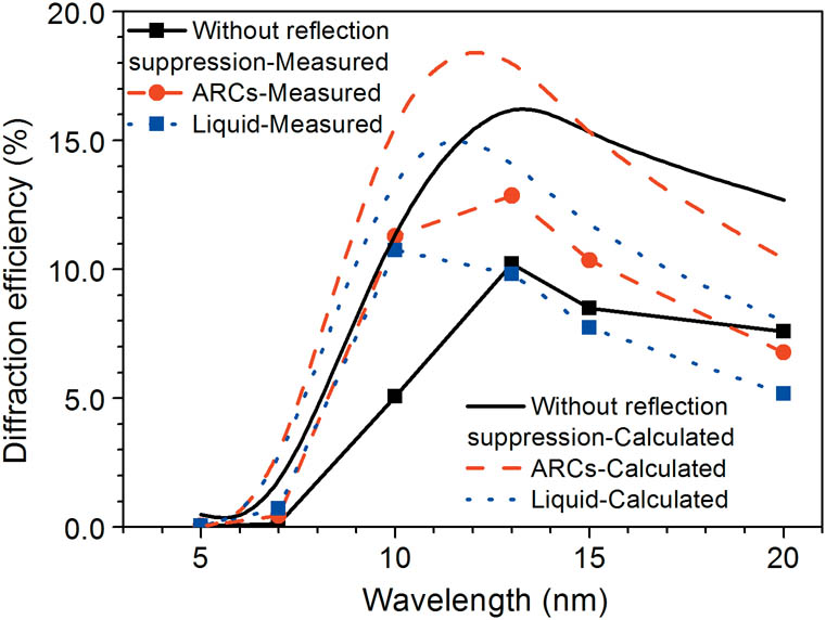
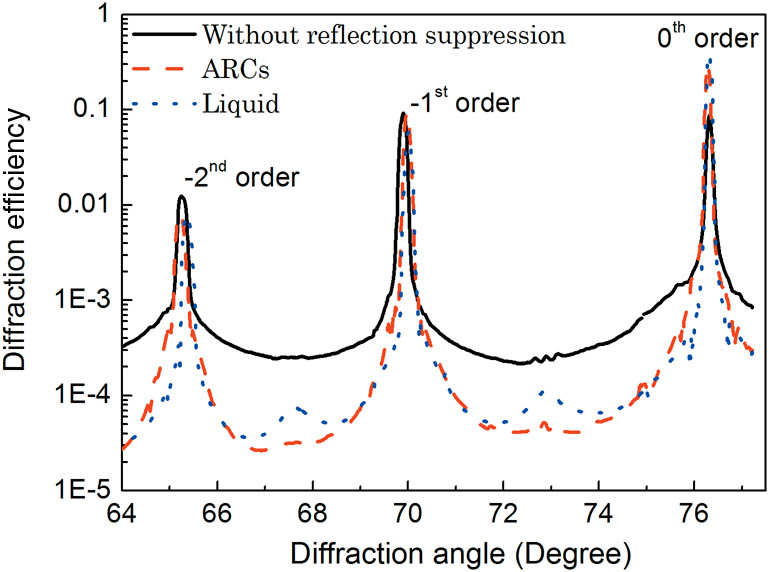
The fabricated resist gratings, including the three instances shown in Fig. 5, were used as etching masks to fabricate soft x-ray laminar gratings with 2400 lines/mm by using ion beam etching and gold-coating deposition. The fabricated elements were characterized at the spectral radiation standard and metrology beamline BL08B of the National Synchrotron Radiation Laboratory of China[12]. Figure 6 shows the measured and calculated efficiencies in the 1st order of the three gratings versus wavelength. The simulated curve was calculated by using the actual groove profile parameters shown in Table 1. The shape of the measured curves is similar for all samples. Moreover, the measured efficiency data fit well (with about 60%–70%) with the simulations. The deviations between the theoretical and experimental efficiency data could have been caused by such factors as the polarization degree of the incident synchrotron light or the profile parameters of the grating and the gold film. The efficiency differences at the 1st order of the three gratings may be attributed to their slight profile difference. Furthermore, to show the efficiency differences of the gratings made by NFH with and without reflection suppression, Figure 7 depicts the diffraction efficiency angular spectrum of the three gratings. With similar efficiencies at the 1st order, the scattered efficiencies between the primary diffraction orders of the gratings fabricated by NFH with either ARCs or the refractive index liquid are approximately one magnitude less than those of the grating by NFH without reflection suppression.

Table 1. Measured Parameters of the Grating Samples

Grating FabricationGroove Density (lines/mm)Groove Depth (nm)Duty Cycle
Using NFH without reflection suppression2397.8±0.314.05±0.140.50±0.01
Using NFH with ARCs2397.9±0.210.04±0.160.50±0.01
Using NFH with refractive index liquid2398.2±0.211.24±0.450.60±0.03

查看所有表

Fig. 6. Measured efficiency at the 1st order of the gold-coated laminar grating samples as a function of wavelength at an incidence angle of 76.78°. The fabrication differences of the samples are indicated by the legend.

下载图片 查看所有图片

Fig. 7. Diffraction efficiency angular spectrum of the gold-coated laminar grating samples at an incidence angle of 76.78° and a wavelength of 13 nm. The fabrication differences of the samples are indicated by the legend.

下载图片 查看所有图片

These results underscore the necessity of reflection suppression during NFH. For gratings by NFH with ARCs or a refractive liquid, the origin of the small peaks between primary diffractions orders needs future investigation.

In conclusion, we demonstrate the applicability of ARCs in NFH setups for the realization of diffraction gratings with low scattered light. With the fabricated samples (line density 2400 lines/mm) we achieve a comparable optical quality of gratings fabricated with NFH enhanced with ARCs and a setup employing a refractive index liquid. However, in comparison to refractive index liquids, our approach with ARCs enables an easier control of the holographic process.

The presented results illustrate the potential of combining the strengths of NFH and EBL, i.e., high throughput, precise critical dimensions, and a large structure flexibility of reflection-reduced phase masks. The results form the basis for further investigations of the transfer relation of the spatial line density distribution between phase masks and resist gratings. This will open a new avenue for the efficient generation of high-quality resist patterns with even higher line densities and varied line spacings.

References

[1] SokolovA. A.EggensteinF.ErkoA.FollathR.KünstnerS.MastM.SchmidtJ. S.SenfF.SiewertF.ZeschkeT. H.SchäfersF., Proc. SPIE9206, 92060J (2014).

[2] LiC.ZhuJ.WangQ., J. Phys. Conf. Ser.425, 162008 (2013).

[3] YangJ.DingY.ZhengZ.WangY.ZhangW.ZhangJ.LiuJ.ShanB.GaoS.RenY.LiuX., Acta Phys. Sin.52, 1427 (2003).WLHPAR1000-3290

[4] ShiZ.ZhaoR.LiW.TuB.YangY.XiaoJ.HuldtS.HuttonR.ZouY., Rev. Sci. Instrum.85, 063110 (2014).RSINAK0034-6748

[5] ChenH.LanH.ChenZ.LiuL.WuT.ZuoD.LuP.WangX., Acta Phys. Sin.64, 075202 (2015).WLHPAR1000-3290

[6] KitaT.HaradaT.NakanoN.KurodaH., Appl. Opt.22, 512 (1983).APOPAI0003-6935

[7] KoikeM.SanoK.GulliksonE.HaradaY.KumataH., Rev. Sci. Instrum.74, 1156 (2003).RSINAK0034-6748

[8] LinH.ZhangL.JinC.ZhouH.HuoT., Chin. Opt. Lett.7, 180 (2009).CJOEE31671-7694

[9] FangL.WuJ.LiuQ.ChenG., Opto-Electron. Eng.33, 88 (2006).

[10] LingJ.ZhangD.HuangY.WangQ.ZhuangS., J. Modern Opt.61, 132 (2014).JMOPEW0950-0340

[11] TanX.JiaoQ.QiX.BayanH., Opt. Express24, 5896 (2016).OPEXFF1094-4087

[12] HeS.LiuY.ZhuJ.LiH.HuangQ.ZhouH.HuoT.WangZ.FuS., Opt. Lett.36, 163 (2011).OPLEDP0146-9592

[13] ZhouQ.PangJ.LiX.NiK.TianR., Chin. Opt. Lett.13, 110501 (2015).CJOEE31671-7694

[14] CaiP.WangJ.WangC.ZengP.LiH., Chin. Opt. Lett.14, 010009 (2016).CJOEE31671-7694

[15] BourginY.JourlinY.ParriauxO.TalneauA.TonchevS.VeillasC.KarvinenP.PassillyN.ZainA. R. M.De La RueR. M.ErpsJ. V.TroadecD., Opt. Express18, 10557 (2010).OPEXFF1094-4087

[16] SunW.LvP.ZhouC.WuJ.WangS., Chin. Opt. Lett.11, 070502 (2013).CJOEE31671-7694

[17] KleyE.-B.ClausnitzerT., in Optical Science and Technology, SPIE’s 48th Annual Meeting, 115 (2003).

[18] AmakoJ.SawakiD., Appl. Opt.51, 3526 (2012).APOPAI0003-6935

Yuanfang Li, Huoyao Chen, Stefanie Kroker, Thomas Käsebier, Zhengkun Liu, Keqiang Qiu, Ying Liu, Ernst-Bernhard Kley, Xiangdong Xu, Yilin Hong, Shaojun Fu. Near-field holography enhanced with antireflection coatings—an improved method for fabricating diffraction gratings[J]. Chinese Optics Letters, 2016, 14(9): 090501.

本文已被 1 篇论文引用
被引统计数据来源于中国光学期刊网
引用该论文: TXT   |   EndNote

相关论文

加载中...

关于本站 Cookie 的使用提示

中国光学期刊网使用基于 cookie 的技术来更好地为您提供各项服务,点击此处了解我们的隐私策略。 如您需继续使用本网站,请您授权我们使用本地 cookie 来保存部分信息。
全站搜索
您最值得信赖的光电行业旗舰网络服务平台!