复合热源钛合金熔丝高质量增材制造工艺研究  下载: 536次
Titanium alloys are lightweight alloys with excellent properties including high strength, high stiffness, and good corrosion resistance. Hence, they are widely used in aerospace, automobile manufacturing, and other fields and are one of the most widely studied engineering materials in the field of additive manufacturing. Metal wire feed deposition forming is an important metal additive manufacturing process that has the advantages of low cost and 100% material utilization rate. However, the process characteristics easily lead to problems of poor surface roughness and low dimensional accuracy of parts, which limits the wide application of this process. Accordingly, to improve the surface roughness and dimensional accuracy of such parts, fine metal wires can be deposited by controlling the energy input. However, a method for obtaining high-quality titanium alloy parts has not been reported in the literature. In this study, the composite heat source of the laser and joule heat is used to fuse and deposit the fine titanium alloy wire with the diameter of 0.3 mm. The influence of process parameters on the geometrical characteristics of the deposited single bead is systematically investigated, and a stable combination of the forming process parameters is obtained. Then, based on a stable single bead, aiming at shape control, high-quality thin-walled parts are obtained using the gradient transition deposition method.
The process uses the synergy of a laser and joule current to deposit metal wires on a traveling substrate. Metal wires are continuously fed into the molten pool for continuous deposition as the substrate moves and rapidly solidify to form continuous smooth single beads. In this experiment, the effects of process parameters on the geometric properties of single bead are systematically studied, metallographic sample of single bead is prepared, and pictures and geometric characteristic data are collected. A high-quality titanium alloy thin wall is deposited by a stable single-layer deposition process parameter combination, the length and wall thickness of thin-walled parts are measured, and the line roughness and surface roughness of the thin-walled titanium alloy are determined. Finally, the thin-walled parts are cut into non-standard tensile specimens to test the mechanical properties in the deposition and travel directions.
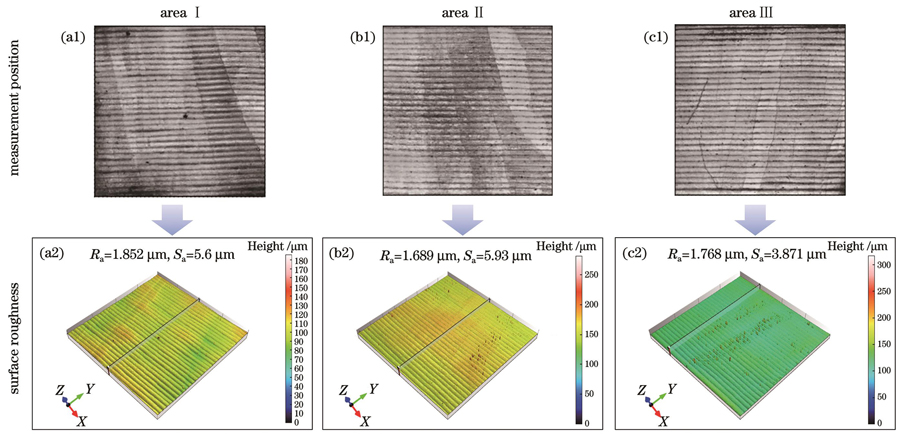
The width and height of the deposited single bead are significantly affected by laser power. Under univariate conditions, with an increase in the laser power, the width of the single bead increases, the height decreases, and the wetting angle decreases (Fig. 3); with an increase in the wire feeding speed, the width remains stable, the height increases, and the wetting angle decreases (Fig. 4); with an increase in the travel speed, the width of the single bead decreases, the height tends to remain stable after reaching a certain speed, and the wetting angle does not change significantly (Fig. 5); the current does not affect the single bead deposition geometric features, but excessive current could worsen the formed morphology (Fig. 6). Thin-walled titanium alloys are deposited based on optimized process parameters, and it is found that the main factors affecting the deposition quality are the heat input and interlayer increment. By controlling the gradient input of the laser power and optimizing the interlayer increment and wire drawing method, the deposition quality is improved, and defects in the deposited parts are avoided. Finally, a titanium alloy thin-walled part without defects and with uniform width and height is obtained (Fig. 14). The average wall thickness of the titanium alloy thin-walled parts without post-treatment is 0.648 mm, with the thickness deviation of 0.004 mm (Fig. 15) and surface roughness (Ra) of 1.776 μm (Fig. 17). Results regarding the mechanical properties show that the tensile strength of the titanium alloy sample is 905.05-957.64 MPa (Fig. 18), and the mechanical properties are comparable to those of forging and casting (Table 3).
In this study, the effects of process parameters on the geometrical characteristics of deposited single bead are investigated using filament melting deposition process with the composite heat source of laser and joule heat. Using the composite energy generated by the laser and joule heat as the heat source and by controlling the heat input, titanium alloy is continuously deposited during the process of heating the wire, and high-quality thin-walled parts can be obtained at low laser power. By optimizing the deposition process, the defects and deficiencies in the deposition process are solved, and a thin-walled titanium alloy part with high surface quality and high dimensional accuracy is obtained. Accordingly, Ra is determined as 1.776 μm. The forming quality is much higher than that of mainstream wire feed additive manufacturing, and the maximum ultimate tensile strength is 957.64 MPa. The mechanical properties are comparable to those of forgings and casting.
1 引言
钛合金作为一种具有高强度、高刚度和良好耐蚀性等优异性能的轻质合金,得到了广泛的研究[1-3]。相对于传统的减材制造,钛合金增材制造工艺灵活性高,有效地解决了复杂结构件加工困难的问题,同时具备快速成形、低成本等优势,在航空航天等领域中具有广阔的应用前景[4-7]。在金属增材制造的主流工艺中,金属熔丝增材制造因具有低成本、接近100%的材料利用率和无污染等优点而受到关注[8],但该工艺往往存在制件表面粗糙度差、尺寸精度低的问题,这制约了它的广泛应用[9]。
在激光熔丝增材制造工艺中,成形质量受激光功率、送丝速度、移动速度等工艺参数的直接影响,已有大量学者对这方面进行了研究。Liu等[10]以试验和建模的方法建立了不同工艺组合的成形数据库,分析了工艺参数对沉积层几何特征的影响,研究表明,移动速度和激光功率对沉积单道的几何特征的影响最为显著,送丝速度对沉积层高度的影响更明显。李凯斌等[11]研究了工艺参数对单道沉积层形貌的影响,研究表明,宏观形貌主要由激光功率、扫描速度和送丝速度主导,而离焦量的影响相对较小;在此基础上,分析了工艺参数对单道沉积层几何特征的影响规律,通过优化激光能量密度和熔丝率获得了稳定的熔覆道。Brandl等[12]研究了激光功率、移动速度与送丝系数对沉积层尺寸的影响,结果表明,随着激光功率的增加,沉积宽度增加、高度减小;移动速度对沉积层的影响与激光功率相反,送丝系数只影响高度不影响宽度。Mok等[13]的研究表明,沉积宽度受激光功率的影响较大,移动速度对沉积高度的影响比激光功率更显著。Wang等[14]探讨了激光和电弧复合制造工艺参数对沉积层几何特征的影响,发现激光功率和移动速度对沉积层有显著影响。以上文献研究选用的激光功率都较高,在高能束的作用下熔池尺寸的控制难度高,制件易产生裂纹、变形等缺陷[15-17]。此外,该工艺逐层沉积的成形特性会使零件表面产生一定程度的阶梯效应,降低了零件的质量和精度,从而增加了后处理成本和交付时间[18]。
针对降低金属熔丝增材制造零件表面粗糙度的措施,已有一些学者进行了探索。Shaikh等[19]以直径为0.1 mm的不锈钢丝为材料,通过优化成形工艺参数,获得了表面粗糙度为8~16 μm的沉积件。Demir[20]提出了微激光细丝沉积技术,以正交建模的方法优化了沉积工艺,获得了尺寸精度较高的薄壁。Li等[21]利用复合热源增材制造工艺对直径为0.3 mm的不锈钢细丝进行了沉积,并通过化学抛光获得了较好的表面质量。上述研究表明,通过控制能量输入来形成小尺寸熔池的方式具有提升金属熔丝沉积制件成形质量的潜力。但关于获得高质量钛合金制件的成形工艺仍未有报道。
综上所述,本文以激光和焦耳热复合热源对直径为0.3 mm的钛合金细丝进行了熔融沉积,系统地研究了激光功率、移动速度、送丝速度和电流对单道沉积层几何特征的影响规律,并获得了稳定成形的工艺参数组合。在此基础上,以控形为主要目标,采用激光功率梯度过渡的沉积方式获得了高质量的薄壁件。研究结果为提升钛合金增材制造零件的表面质量和尺寸精度提供了参考。
2 材料及方法
2.1 试验材料
试验使用的基板和金属丝材均为Ti-6Al-4V钛合金,基板厚度为5 mm,金属丝直径为0.3 mm。为了使钛合金基板对激光有更好的能量吸收,用砂纸对基板表面进行打磨处理,利用无水乙醇冲洗表面杂质,烘干后使用。材料的主要化学成分如
表 1. Ti-6Al-4V的化学成分
Table 1. Chemical compositions of Ti-6Al-4V
|
2.2 工艺原理
激光和焦耳热细丝熔融沉积原理及装置如

图 1. 激光和焦耳热复合热源细丝沉积工艺。(a)原理图;(b)试验装置图
Fig. 1. Fine-wire deposition process with laser and joule heat hybrid source. (a) Schematic; (b) experimental device
2.3 试验方法
单道沉积层的形状控制对增材制件的整体形貌至关重要。单道沉积层的几何特征主要体现在宽度(D)、高度(H)和润湿角(θ),如
表 2. 激光和焦耳热复合热源细丝沉积试验参数
Table 2. Experimental parameters of fine-wire deposition with laser and joule heat hybrid source
|
3 结果与讨论
3.1 激光功率

图 3. 激光功率对单道几何特征的影响。(a)宽度和高度;(b)润湿角
Fig. 3. Effects of laser power on geometric characteristics of single bead. (a) Width and height; (b) wetting angle
如

图 4. 不同激光功率下的成形形貌和截面。(a)P=75 W;(b)P=125 W;(c)P=200 W
Fig. 4. Forming morphologies and cross sections under different laser powers. (a) P=75 W; (b) P=125 W; (c) P=200 W
3.2 送丝速度

图 5. 送丝速度对单道几何特征的影响。(a)宽度和高度;(b)润湿角
Fig. 5. Effects of wire feed speed on geometric characteristics of single bead. (a) Width and height; (b) wetting angle

图 6. 不同送丝速度下的成形形貌和截面。(a)Vf=60 mm/min;(b)Vf=240 mm/min;(c)Vf=360 mm/min
Fig. 6. Forming morphologies and cross sections under different wire feed speeds. (a) Vf=60 mm/min; (b) Vf=240 mm/min; (c) Vf=360 mm/min
然而,送丝速度的增大将引起单道沉积层的润湿角度增加。当送丝速度超过300 mm/min时,单道的润湿角超过50°,这将增强阶梯效应,影响沉积的表面质量。小的送丝速度对应较小的润湿角,但沉积高度不足,甚至没有光滑连续的成形样貌。此外,当送丝速度过快时,送入熔池的丝材无法完全熔化,从而形成递送阻力,影响送丝稳定形,使沉积层高度随沉积距离的增加而逐渐下降,如
3.3 移动速度

图 7. 移动速度对单道几何特征的影响。(a)宽度和高度;(b)润湿角
Fig. 7. Effects of traveling speed on geometric characteristics of single bead. (a) Width and height; (b) wetting angle

图 8. 不同移动速度下的成形形貌和截面。(a)VS=30 mm/min;(b)VS=150 mm/min;(c)VS=300 mm/min
Fig. 8. Forming morphologies and cross sections under different travel speeds. (a) VS=30 mm/min; (b) VS=150 mm/min; (c) VS=300 mm/min
3.4 焦耳电流

图 9. 电流对单道几何特征的影响。(a)宽度和高度;(b)润湿角
Fig. 9. Effects of joule current on geometric characteristics of single bead. (a) Width and height; (b) wetting angle

图 10. 不同电流下的成形形貌和截面。(a)I=4 A;(b)I=6 A;(c)I=10 A
Fig. 10. Forming morphologies and cross sections under different currents. (a) I=4 A; (b) I=6 A; (c) I=10 A
3.5 稳定成形参数组合的验证
为了验证单道沉积试验中稳定成形参数组合下的实际沉积效果,选择激光功率为125 W、送丝速度为240 mm/min、移动速度为300 mm/min、电流为8 A进行单层沉积。如
4 钛合金薄壁件的成形及其质量测试
4.1 薄壁件的成形工艺及优化
在激光熔丝增材制造工艺中,薄壁结构的沉积和单道沉积存在很大区别。由于逐层往复沉积的工艺特性,薄壁成形经历数次热循环,形成热累积,需要实时调整工艺参数以降低热累积的影响。除工艺参数外,层间增量(ΔZ)会影响熔丝的过渡状态,最终改变薄壁结构的表面形貌。因此,主要通过调整激光功率和层间增量来控制薄壁的成形。

图 12. 不同工艺参数下的薄壁形貌。(a)P=50 W;(b)P=175 W;(c)P=100 W
Fig. 12. Thin wall morphologies under different process parameters. (a) P=50 W; (b) P=175 W; (c) P=100 W
其次,层间增量ΔZ是影响熔丝过渡的主要因素。试验使用的金属丝直径较小,对层间增量的控制精度要求更高。过大的ΔZ使送出的金属丝没有接触沉积层就被熔化,形成熔滴滴落,影响沉积形貌,如

图 13. 缺陷对薄壁成形的影响。(a)层间增量过大;(b)丝材球化;(c)沉积起点突起
Fig. 13. Effects of defects on thin wall forming. (a) Interlayer increment is too large; (b) wire spheroidization; (c) protrusions at deposition origin
在薄壁成形过程中,控制热输入对于解决薄壁坍塌和层间结合差问题十分关键。然而,激光功率大幅度变化会影响沉积层的几何尺寸,从而影响沉积表面质量。为了避免这种现象的出现,采用激光功率梯度过渡的方式进行沉积。合适的激光功率有助于获得饱满的沉积形貌和良好的几何特征,因此,选择在125 W的激光功率下沉积至第3层。为了避免热量累积形成坍塌,选择在100 W的激光功率下沉积至第10层;然后,过渡沉积12层,降低激光功率至75 W。热输入的减小使沉积层的宽度和高度发生微小变化,这对ΔZ的控制要求更高。通过判断闭合回路中是否有电流变化来确定送出的丝材是否与沉积层接触,接触前、后的高度差就是层间增量ΔZ的实际值。研究发现,11~22层的层间增量在0.126~0.133 mm区间波动,在23层之后稳定的ΔZ为0.131 mm。
除上述因素外,沉积终点金属丝的球化也是影响成形质量的原因之一。在沉积过程中,金属丝被不断地送入到小尺寸的熔池中,直至单层沉积结束。在激光能量的作用下,送出的丝材被灼烧而球化,使下一层起点的沉积量增大,逐层累积造成沉积起点凸起,如

图 14. 薄壁成形过程及试样展示。(a)薄壁沉积过程;(b)成形薄壁件;(c)三角形薄壁展示
Fig. 14. Thin wall forming process and sample display. (a) Thin wall deposition process; (b) forming thin-walled parts; (c) triangular thin wall display

图 15. 薄壁尺寸测量结果。(a)长度;(b)壁厚
Fig. 15. Measured results of thin wall dimensions. (a) Length; (b) wall thickness
4.2 表面粗糙度检测
使用共聚焦显微镜测量薄壁件的表面粗糙度,选择4 mm×4 mm的区域,经过调平、滤波等处理,获得了表面形貌图和轮廓图,具体选区如
为了保证线粗糙度的准确性,测量时避开噪点存在的区域,线粗糙度的测量位置如

图 17. 薄壁件表面粗糙度检测。(a1)(a2)区域Ⅰ;(b1)(b2)区域Ⅱ;(c1)(c2)区域Ⅲ
Fig. 17. Surface roughness test of thin-walled parts. (a1)(a2) Area Ⅰ; (b1)(b2) area Ⅱ; (c1)(c2) area Ⅲ
4.3 力学性能
在室温下,利用拉伸试验机对试样进行抗拉性能测试。由于打印件尺寸的限制,以非标样进行测试,取样尺寸如

图 18. 力学性能测试。(a)拉伸试样尺寸;(b)应力-应变曲线
Fig. 18. Mechanical property test. (a) Tensile specimen size; (b) stress-strain curves
表 3. 不同工艺下的力学性能比较
Table 3. Comparison of mechanical properties under different processes
|

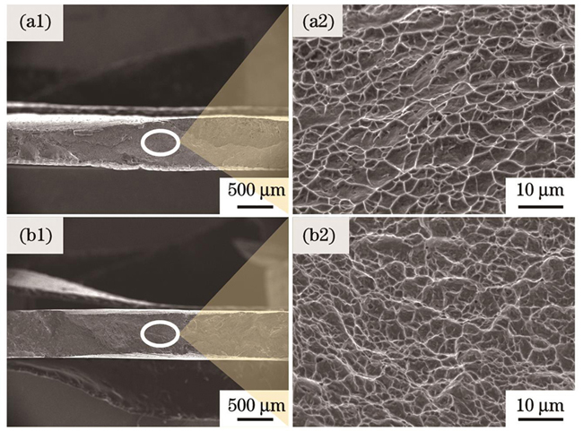
图 19. 断口的宏微观形貌。(a1)(a2)移动方向;(b1)(b2)沉积方向
Fig. 19. Macro/micro morphology of fracture. (a1)(a2) Traveling direction; (b1)(b2) deposition direction
5 结论
基于激光和焦耳热钛合金细丝沉积工艺,以控形为主要目标,讨论了工艺参数对单道沉积层几何特征的影响规律,通过控制沉积过程中的热输入和层间增量,获得了较高质量的沉积薄壁。主要结论如下:
1)利用焦耳热对金属丝进行预热,并将其送入到低功率激光加热形成的小尺寸熔池中进行连续沉积,成形件具有良好的形貌。以此方式对直径为0.3 mm的钛合金丝材进行沉积,在功率为125 W、送丝速度为240 mm/min、移动速度为300 mm/min和电流为8 A时,单道沉积层的宽度和高度均匀,表面光滑。
2)在单一变量条件下,随着激光功率的增加,宽度增大,高度减小;随着送丝速度的增加,宽度稳定,高度增加;随着移动速度的增加,宽度和高度均减小,而高度在达到一定值后趋于稳定;通入的焦耳电流对单道沉积层的几何特征并未有明显影响,但过大的电流会影响成形质量。
3)通过改变激光功率来控制工艺的热输入,可以有效提升沉积质量。在优化成形缺陷的基础上,以25 W的激光功率梯度过渡的形式,减小激光功率至75 W,成功沉积了尺寸稳定、厚度均匀的薄壁。薄壁结构无明显缺陷,在未经后处理的情况下表面粗糙度Ra可达1.776 μm,优于主流的金属送丝增材制造工艺。
4)激光和焦耳热熔丝工艺下的钛合金在移动方向上的抗拉强度为(918.91±9.54)MPa,在沉积方向上的抗拉强度为(926.516±22.52)MPa,成形件具有一定的塑性特征,且断口均表现为韧性断裂。
[1] 董春林, 谭锦红, 林志成, 等. 钛合金增材制造技术研究进展[J]. 金属加工(热加工), 2020(7): 16-21.
Dong C L, Tan J H, Lin Z C, et al. Research progress of titanium alloy additive manufacturing technology[J]. MW Metal Forming, 2020(7): 16-21.
[2] Liu S Y, Shin Y C. Additive manufacturing of Ti6Al4V alloy: a review[J]. Materials & Design, 2019, 164: 107552.
[3] 李长富, 任皓显, 步佳颀, 等. 增材制造的含硼Ti-6Al-4V钛合金的组织与性能研究[J]. 中国激光, 2021, 48(18): 1802014.
[4] Liu Z Y, He B, Lü T Y, et al. A review on additive manufacturing of titanium alloys for aerospace applications: directed energy deposition and beyond Ti-6Al-4V[J]. JOM, 2021, 73(6): 1804-1818.
[5] Lin Z D, Song K J, Yu X H. A review on wire and arc additive manufacturing of titanium alloy[J]. Journal of Manufacturing Processes, 2021, 70: 24-45.
[6] Herzog D, Seyda V, Wycisk E, et al. Additive manufacturing of metals[J]. Acta Materialia, 2016, 117: 371-392.
[7] 顾冬冬, 张红梅, 陈洪宇, 等. 航空航天高性能金属材料构件激光增材制造[J]. 中国激光, 2020, 47(5): 0500002.
[8] 章敏. 送粉式和送丝式的钛合金激光增材制造特性研究[D]. 哈尔滨: 哈尔滨工业大学, 2013: 52-54. 10.14257/astl.2013.29.90
ZhangM. Research on laser additive manufacturing characteristics of titanium alloy with powder and wire[D]. Harbin: Harbin Institute of Technology, 2013: 52-54.
[9] Ding D H, Pan Z X, Cuiuri D, et al. Wire-feed additive manufacturing of metal components: technologies, developments and future interests[J]. The International Journal of Advanced Manufacturing Technology, 2015, 81(1): 465-481.
[11] 李凯斌, 李东, 刘东宇, 等. 光纤激光送丝熔覆修复工艺研究[J]. 中国激光, 2014, 41(11): 1103006.
[12] Brandl E, Michailov V, Viehweger B, et al. Deposition of Ti-6Al-4V using laser and wire, part II: hardness and dimensions of single beads[J]. Surface and Coatings Technology, 2011, 206(6): 1130-1141.
[13] Mok S H, Bi G J, Folkes J, et al. Deposition of Ti-6Al-4V using a high power diode laser and wire, Part I: Investigation on the process characteristics[J]. Surface and Coatings Technology, 2008, 202(16): 3933-3939.
[14] Wang C, Suder W, Ding J L, et al. Wire based plasma arc and laser hybrid additive manufacture of Ti-6Al-4V[J]. Journal of Materials Processing Technology, 2021, 293: 117080.
[15] 姚讯杰, 王佳玮, 杨雁程, 等. 金属构件激光增材制造缺陷产生机理及控制机制探究[J]. 中国激光, 2022, 49(14): 1402802.
[16] Wu B T, Pan Z X, Ding D H, et al. A review of the wire arc additive manufacturing of metals: properties, defects and quality improvement[J]. Journal of Manufacturing Processes, 2018, 35: 127-139.
[17] Fritz K, Kristian A, Nils K, et al. Wire-based laser metal deposition for additive manufacturing of TiAl6V4: basic investigations of microstructure and mechanical properties from build up parts[J]. Proceedings of SPIE, 2017, 10095: 100950U.
[18] Maleki E, Bagherifard S, Bandini M, et al. Surface post-treatments for metal additive manufacturing: progress, challenges, and opportunities[J]. Additive Manufacturing, 2021, 37: 101619.
[19] Shaikh M O, Chen C C, Chiang H C, et al. Additive manufacturing using fine wire-based laser metal deposition[J]. Rapid Prototyping Journal, 2019, 26(3): 473-483.
[20] Demir A G. Micro laser metal wire deposition for additive manufacturing of thin-walled structures[J]. Optics and Lasers in Engineering, 2018, 100: 9-17.
[21] Li B B, Wang B W, Zhu G, et al. Low-roughness-surface additive manufacturing of metal-wire feeding with small power[J]. Materials, 2021, 14(15): 4265.
[22] 温鹏, 郑世卿, 荻崎贤二, 等. 填充热丝激光窄间隙焊接的试验研究[J]. 中国激光, 2011, 38(11): 1103004.
[23] Liu S, Liu W, Kovacevic R. Experimental investigation of laser hot-wire cladding[J]. Proceedings of the Institution of Mechanical Engineers, Part B: Journal of Engineering Manufacture, 2017, 231(6): 1007-1020.
[24] Baufeld B, Brandl E, van der Biest O. Wire based additive layer manufacturing: comparison of microstructure and mechanical properties of Ti-6Al-4V components fabricated by laser-beam deposition and shaped metal deposition[J]. Journal of Materials Processing Technology, 2011, 211(6): 1146-1158.
Article Outline
冯启高, 王琳鑫, 王磊, 马利杰, 汤永凯, 李波波. 复合热源钛合金熔丝高质量增材制造工艺研究[J]. 中国激光, 2023, 50(8): 0802306. Qigao Feng, Linxin Wang, Lei Wang, Lijie Ma, Yongkai Tang, Bobo Li. Research on High-Quality Additive Manufacturing Process of Titanium Alloy Fuse with Composite Heat Source[J]. Chinese Journal of Lasers, 2023, 50(8): 0802306.


