本振调制型高重复频率远距离脉冲激光相干测距
When high repetition frequency integrated transceiver pulsed laser coherent method is utilized to measure static target distance, the maximum unambiguous distance caused by high repetition frequency is shortened on the one hand. On the other hand, reflected light is formed due to the reflection from the lens end face and the light leakage of the circulator at the time of emission. So the echo light will be submerged in the reflected light when it arrives during the pulse emission period. It is impossible to detect the echo light within the pulse emission time. Multiple blind range points and ambiguous distance problem appear. The traditional staggered pulse repetition frequency method requires frequency switching to obtain multiple sets of measurement data under different conditions. The control process is complicated and the echo light is still indistinguishable from the emitted light. A new scheme, high repetition frequency long-distance pulsed laser coherent ranging based on local oscillator modulation, is proposed in this paper. The maximum unambiguous distance determining factor is transferred from the pulse signal repetition frequency to the local oscillator modulation period. It expands the unambiguous range and solves the multiple blind distance points problem to make the measurement range continuous. There is no need to switch the repetition frequency, and the difficulty of system control is reduced. At the same time, requirements of the repetition frequency adaptability with the laser amplifier are reduced.
In pulsed laser coherent ranging, laser light is divided into two parts. One part is chopped and modulated to form pulsed light sent to the target, and the other is continuous local oscillator light. The proposed scheme mainly performs periodic chirp modulation on the continuous local oscillator light. And different pulse start frequencies are set according to the corresponding time relationship between the transmitted pulse signal and the local oscillator light. The modulation slopes of all pulse repetition frequencies are consistent. In order to make the measurement accuracy higher, the pulse compression method is used for data processing. So the slope of the optical pulse modulation is different from that of the local oscillator modulation. When the echo signal is coherent with the local oscillator signal, there will be two different effects. Within the local oscillator repetition period, one effect is that the pulse coherent signal with the same starting frequency is generated [Fig. 6(a)]. The other is that two different pulse coherent starting frequency signals are generated [Fig. 6(b)]. When the initial frequencies are different, the echo data are grouped according to the pulse repetition period that starts from the triggering time of the local oscillator modulation. The matching results of each group are analyzed. The number of pulses with the first initial frequency and the pulse compression results with the second initial frequency are recorded. Based on the recorded results, the target distance can be obtained by simple calculation.
In experiments, three acousto-optic modulators (AOMs) are mainly used. The first AOM is used as a pulse signal optical modulator. Its design parameters include 200 MHz initial frequency,
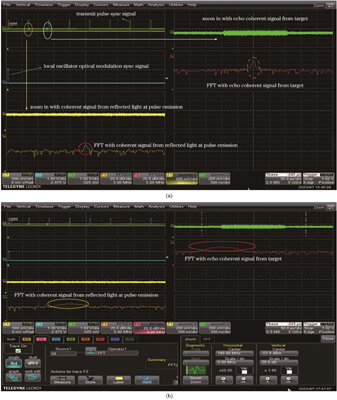
Two measurement schemes with and without the local oscillator modulation are compared. Data acquisition and processing are performed. Relevant measurement results are obtained (Tables 3 and 4). With the local oscillator modulation high repetition frequency ranging scheme, the measured round-trip distances are 7.9608 km, 36.5156 km, and 58.1052 km, respectively. The corresponding accuracies are 2.7274 m, 5.1906 m, and 7.819 m. Since the 36.5 km delay line exceeds 19.2 km corresponding to a pulse repetition period, the measured distance based on the scheme without local oscillator modulation is 17.3 km (Table 3). An ambiguity phenomenon occurs and the target cannot be accurately measured. However, the measured distance 36.5 km can be obtained based on the local oscillator modulation, which matches the actual length of the optical fiber. Under the experimental condition of 58.1 km delay line, the data processing result is 0 based on the scheme without local oscillator modulation. The reason is that the echo light and the emitted light partially overlap in the time domain. The measurement scheme with local oscillator modulation shows advantage in frequency domain. Although these two pulsed lasers illuminate the detector surface simultaneously, their information in frequency domain is separated. The echo optical signal can be effectively distinguished through the matching filter algorithm. The specific distance value of 58.1052 km is obtained.
Some problems exist in the high repetition frequency integrated transceiver pulsed laser coherent ranging, including that the unambiguous distance is short and the echo signal light cannot be received normally at the moment of emission. The local oscillator modulation pulsed laser coherent ranging based on local oscillator and signal double-chirp modulation proposed in this paper overcomes the short unambiguous distance and multiple blind distance points. The measurement results with 36.5 km and 58.1 km delay fibers are obtained with the conditions including
1 引言
激光雷达凭借着探测精度高、抗干扰能力强、多普勒敏感等特点,在汽车自动驾驶[1]、星间通信[2]、空间测距[3]、环境科学[4]等应用中受到广泛重视,特别是在中远程测距中,对激光雷达有着迫切需求。现代化军民应用需要高数据率的测量结果,这对激光雷达的脉冲发射频率提出了较高的要求。当目标距离较远时,较高的重复频率会产生距离模糊现象,降低测量准确度。一般主要从相位[5-6]、频率[7-8]和发射周期三种编码调制方式解决该问题。其中,最常用的是利用基于发射周期编码的参差重复频率方案进行模糊解算[9],采用单一激光源通过切换重复频率获取不同条件下的测量结果,控制过程较为复杂,对激光器要求较高;后续解算采用的是余数定理法及相关的查找表法[10],对余数冗余提出要求[11]。依赖不同重复频率的双梳测距[12]虽然不需要切换发射频率,但是激光源设计复杂;基于游标效应的解算方法在本质上与余数定理一致,余数的准确读取对距离解算的准确性至关重要。
近年来,为解决不同场景下激光雷达的距离模糊问题,很多新方案被提出。文献[13]提出的距离周期扩展方法在机载雷达中得到应用,其主要是利用强目标检测门限、帧间熵门限以及弱目标检测门限进行阈值检测及目标提取,增加了数据处理难度;文献[14]利用阵元脉冲编码的设计方法,在阵元数大于模糊区数的基础上,对不同编码形式的解模糊性能进行分析,不适合单一阵元测量;文献[15]采用改进筛选法对球载雷达多目标探测进行解模糊计算;文献[16]采用两步激光频率调制方案来扩展不模糊距离,在流程控制和处理时间方面有所消耗。在单光子激光测距中,文献[17]采用扩展伪随机码调制激光方案消除距离模糊,文献[18]对不同重复频率下的伪随机编码方式进行对比,文献[19]提出混沌单光子激光概念,利用随机序列编码的形式不但克服了距离模糊问题,而且提升了信噪比(SNR)。
在高重复频率收发一体式单元激光脉冲相干测距中,单一高重复频率导致不模糊距离变短,参差重复频率对系统控制和解算提出较高要求;同时由于发射时刻镜头端面反射和环形器光泄漏会在激光发射时刻反射出射光,跨周期回波光会淹没在镜头反射光内,导致无法探测脉冲周期内近距离目标以及整脉冲周期对应的目标。受此影响,高重复频率收发一体式激光相干测距在远距离测量方面存在严重的多点盲距和模糊问题。
本文在已有脉冲激光相干测距系统的基础上,对发射波形和本振波形进行双重改进,提出基于调制本振的高重复频率脉冲激光雷达波形设计方案及相关解算方法,同时对该方案的盲距和距离模糊问题进行分析讨论。在仿真和系统实验方面,通过与已有发射系统及相关解算方法进行对比,表明该方案达到了消除距离模糊、缩小盲距范围的目的,为高重复频率远距离激光相干测距提供了一种解决办法。
2 相干激光雷达模型
相干激光雷达的基本原理是将激光种子源发射的连续激光分为两路,一路为本振光路,一路为信号光路。对信号光路激光进行时间、频率等调制,经过光放大器、发射镜头照射到待测目标。目标散射的回波信号支路光与本振支路光经光合束器(BC)和光电探测器(PD)转化为电信号,对探测到的电信号进行数据处理,解算出目标特征信息,如
激光种子源出射激光表示为
式中:A为信号幅度;
经分束器和调制器后,脉冲信号光为
式中:
设激光照射到目标并返回共经历时间
式中:
本振支路信号光为
式中:
经过合束器和光电探测器后,利用探测器平方律特性并受探测带宽限制,可探测到的相干电流信号
式中:
对电流信号进行数据采集和快速傅里叶变换(FFT)处理,根据
3 信号调制设计与解算分析
3.1 系统方案
与
基于本振线性调制的高重复频率收发一体脉冲激光相干测距系统如

图 2. 基于本振线性调制的高重复频率收发一体脉冲激光相干测距实施方案
Fig. 2. Implementation scheme of pulsed laser coherent ranging based on local oscillator linear modulation with high repetition frequency transceiver
触发信号源分别发射第一、第二触发信号,时序关系如
3.2 波形方案设计
在基于线性调频本振的高重复频率远距离脉冲激光测距中,对调制信号进行如下设计。根据系统要求的最远可探测距离
式中:c为光速。
调制器1接收到触发信号时,激光种子源分出的本振光产生频率f从

图 4. 加载到种子源光频率上的驱动时频分析示意图
Fig. 4. Time-frequency analysis diagram of drive loaded on optical frequency of seed laser
信号光支路经过受驱动单元控制的光调制器2,得到的光脉冲信号调频示意图如

图 5. 信号光经调制器后的时频分析示意图
Fig. 5. Time-frequency analysis diagram of signal light after passing through modulator
对于第n(n=1,2,3,…,N)个脉冲,其调制频率为
式中:
式中:
为解算方便,不妨设
3.3 距离解算
在激光相干探测过程中,信号光经环形器后与本振光进行合束,合束的光进入探测器。由于光电探测器无法直接探测到光频,根据相干检测基本原理,本振光和信号光合束后,产生的和频项无法探测,只能探测差频项,即回波信号光与本振信号光频率之差。
根据3.2节的设计方案,设目标处于距离S处,经过
回波信号光频率为
差频
式中:
由此可知,

图 6. 不同条件下N个脉冲差频结果示意图。(a)
Fig. 6. Schematic diagram of difference frequency results of N pulses. (a)
由上述分析可知,差频结果与N无关,得到的频率差啁啾信号带宽为
对匹配滤波器进行如下设计。对于固定目标来说,其差频
式中:
基于所述频率范围拟合差频特征的频率,满足
式中:r为拟合时间,满足
利用该方法设计的匹配滤波器如
首先对采集信号进行时频分析处理,以本振触发信号为同步基准,当出现两类时频结果时,如
不同延时条件下第N个脉冲差频匹配滤波结果如

图 8. 不同延时条件下,第N个脉冲差频匹配滤波结果
Fig. 8. Matching filter results on the Nth pulse difference frequency under different delay conditions
利用最后一组匹配输出结果,得到待测目标距离
式中:
3.4 模糊距离与盲距分析
3.4.1 盲距问题
采用收发一体脉冲激光测距时,在发射时刻,会有部分信号光因镜头面反射和环形器光泄漏而直接返回,且该部分信号光功率较强,一般工程上会在发射时刻采取探测器关断的方式。但这种方式会导致各个发射信号脉宽时间内无法探测回波信号,在远距离目标探测时,会出现多个盲距点,如
若采用成熟的参差重复频率方式,同样存在盲距点问题:目标返回光出现的时间恰好处在多种重复周期对应的最小公倍数上(如
以参差双重复频率为例,重复周期分别为

图 11. 基于本振调制和参差双重复频率的方案的测不准时间段对比。(a)本振调制方案;(b)参差双重复频率方案
Fig. 11. Comparison of uncertain time periods based on local oscillator modulation and double staggered pulse repetition frequencies. (a) Measurement scheme based on local oscillator modulation; (b) measurement scheme based on double staggered pulse repetition frequencies
在收发一体式高重复频率远距离激光脉冲相干探测方案下,受高重复频率距离模糊和探测器发射时刻关断影响,存在45组距离测不准区域,造成距离测量不连续。而基于本振调制的测量方案在目标距离除发射脉宽对应300 m以内的近距离目标无法测量外,远距离探测不受影响。若提高参差重复频率变化数量,在流程控制和数据解析上均会增加难度。
3.4.2 模糊距离
在高重复频率脉冲激光测距中,最大不模糊距离与信号光脉冲重复频率无关,仅与本振光重复频率有关。因此,在远距离测距时,无需通过控制触发时间改变信号光重复频率,进行多重复频率解模糊计算,仅通过本振光重复频率的设计,即可实现远距离测量。最远可探测距离的计算如
4 仿真分析
利用数据处理软件,对本振光信号频率调制、出射光信号频率调制、匹配滤波器、距离信号处理进行仿真。其中各信号参数设计如
在光基频上调制本振光信号波形如
表 1. 仿真信号设计参数
Table 1. Design parameters of simulation signal
|
表 2. 设置目标参数与仿真结果
Table 2. Target setting parameters and simulation results
|

图 14. 光基频上调制发射光信号波形。(a)整体波形;(b)局部放大
Fig. 14. Transmitted optical signal waveform modulated at optical fundamental frequency. (a) Overall waveform; (b) partially enlarged view
在不同能见度条件下,
利用下式进行衰减系数计算:
式中:
通过计算,得到

图 15. 处于不同距离处的目标仿真结果。(a)1.2 km;(b)7.5 km;(c)35 km
Fig. 15. Simulation results of targets at different distances. (a) 1.2 km; (b) 7.5 km; (c) 35 km
当目标处于1.2 km处时(此时处于发射脉冲的盲距内),结果如
随着探测距离的增加,激光回波能量因大气衰减呈指数化减小。在其他测距影响因素包括镜头透过率、目标面积、接收口径面积等参数恒定且理想的情况下,当能见度为23.5 km时,利用

图 16. 回波信噪比、检测输出信噪比与目标距离之间的关系
Fig. 16. Echo RSN and detection output RSN versus target distance
5 实验平台搭建与数据分析
为检验基于本振调制的高重复频率相干测距方案的可行性,在实验室条件下利用激光器、信号发生器、声光调制器、镜头、探测器、分束器等器件搭建了该测试平台,频率调制采用线性度较好的外调制方案。
其中,信号发生器产生3组相同的触发信号,分别给予本振调频数据生成器、信号调频数据生成器以及示波器。信号调频数据生成器在接到外触发信号后,产生以脉宽
激光器种子光为1550 nm连续波激光器,功率为30 mW,经1∶9分束器分成两部分,10%作为本振光,90%作为信号光。实验室内为模拟光环行器在收发一体式激光相干测距中的影响,采用收发双镜头。经过调制的信号光经过1∶99分束器,99%作为照射目标的信号光,1%模拟光环形器1端到3端的泄漏光信号。当照射目标光信号从待测物体返回后,经过接收镜头,与1%的光环行器模拟信号合束,再与调制后的本振光支路合束,进入探测器,利用示波器进行数据采集和分析。
为对比相干基本方案与本振调制型相干测距方案在距离模糊和盲距方面的表现,将待测目标距离设定为7.96 km、36.5 km和58.1 km附近。由于实验场地受限,外界自然环境难以找到符合条件的目标,因此采用空间目标与光纤延迟线相结合的方式进行对比验证,即在接收镜头后接入光纤延迟线延长光经过的距离。
首先利用第2节所介绍的本振不调制固定载频脉冲激光相干方案对这3个目标进行测量。在模拟仿真过程中,为了显示各信号特征,将调制斜率设置得较大,但在实验中,考虑到各器件能达到的性能指标,进行参数设计如下:脉冲为
表 3. 本振不调制脉冲激光相干雷达目标测量结果
Table 3. Pulsed laser coherent radar target measurement results without local oscillator modulation
|
表 4. 本振调制型脉冲激光相干雷达目标测量结果
Table 4. Pulsed laser coherent radar target measurement results with local oscillator modulation
|

图 17. 36.5 km目标不同调制方案测量结果。(a)本振不调制固定载频脉冲激光相干雷达目标测量结果;(b)本振调制型脉冲激光相干雷达目标测量结果
Fig. 17. Measurement results of different modulation schemes for target distance (delay line) of 36.5 km. (a) Fixed carrier frequency pulsed laser coherent radar target measurement results without local oscillator modulation; (b) pulsed laser coherent radar target measurement results with local oscillator modulation
从
目标A处在单脉冲发射重复周期内,不会产生距离模糊和盲距,利用第2节所介绍的测量方案进行距离度量,并将
目标B的回波光信号落于下一个脉冲重复周期内,在本振不调制固定载频脉冲激光相干测量方案中会产生距离模糊,测量结果平均值只有17.3195 km。而采取本振调制的高重复频率相干测距方案可获得36.5156 km的测量结果平均值。在该时间段内,存在本振光、发射脉冲光和返回信号光同时抵达探测器,发生三波束混频的情况。三波束混频导致三种差频产生,除了本振信号和发射脉冲光信号相干的啁啾信号以及本振光信号和返回信号光相干的啁啾信号外,还存在发射脉冲光和返回信号相干产生的单频差频信号,由于采用脉冲压缩的方法,该单频信号对结果影响较小。
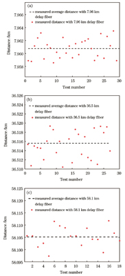
本振不调制固定载频脉冲激光相干方案在不调整脉冲重复周期的条件下,目标C的返回光信号恰好落于目标发射时间段,受到镜头反射光的影响,产生距离盲距。利用第2节所介绍的相干测量方案无法获取测量值,而基于本振调制的高重复频率相干测距方案可以获得58.1052 km的测量结果平均值。测距系统的精度与接收信号信噪比、采样精度等密切相关。实验中,利用距离镜头1 m的合作目标,组合不同长度的延迟光纤,采集40次测量结果,提取有效数据,得到本振调制型脉冲各组数据分布,如

图 18. 本振调制型脉冲激光相干测距不同延迟光纤测量结果。(a)7.96 km;(b)36.5 km;(c)58.1 km
Fig. 18. Measurement results with different lengths of delay fiber based on local oscillator modulation pulsed laser coherent ranging. (a) 7.96 km; (b) 36.5 km; (c) 58.1 km
综合以上实验结果和分析对比可知,基于本振调制型的脉冲激光相干测距可以有效避免高重复频率远距离探测的距离模糊问题(目标B测量),同时克服了收发一体式脉冲激光测距在发射时刻由于镜头端面反射及环形器光泄漏导致的多盲距问题(目标C测量)。
6 结论
本文设计了一种基于本振调制的高重复频率远距离脉冲激光相干测距系统。根据激光相干测距理论,建立基于本振光、发射脉冲光的不同斜率线性调频方案,并利用采集的相干信号进行脉冲压缩数据处理,推导出距离解算办法。通过盲距和模糊距离的理论分析,证明该方案能够解决远距离高重复频率条件下距离模糊严重、参差重复频率存在多个距离模糊区间、收发一体式测距盲距点较多等问题。所设计的方案在信号光为
[1] Kim G, Ashraf I, Eom J, et al. Concurrent firing light detection and ranging system for autonomous vehicles[J]. Remote Sensing, 2021, 13(9): 1767.
[2] 邓汝杰, 张艺斌, 刘河山, 等. 太极计划中的星间激光测距地面电子学验证[J]. 中国光学(中英文), 2023, 16(4): 765-776.
[3] 李祝莲, 翟东升, 汤儒峰, 等. 基于532 nm波长的空间碎片白天激光测距研究与试验[J]. 激光与光电子学进展, 2022, 59(11): 1112003.
[4] 徐荷, 孙迪峰, 李健兵. 相干测风激光雷达回波相干性分析[J]. 激光与光电子学进展, 2023, 60(14): 1428003.
[5] Xu J W, Zhang Y H, Liao G S, et al. Resolving range ambiguity via multiple-input multiple-output radar with element-pulse coding[J]. IEEE Transactions on Signal Processing, 2020, 68: 2770-2783.
[6] Niu S L, Zhu D Y, Jin G D, et al. A novel transmitter-interpulse phase coding MIMO-radar for range ambiguity separation[J]. IEEE Transactions on Geoscience and Remote Sensing, 2022, 60: 5238216.
[7] Hanto D, Pratomo H, Rianaris A, et al. Time of flight lidar employing dual-modulation frequencies switching for optimizing unambiguous range extension and high resolution[J]. IEEE Transactions on Instrumentation and Measurement, 2023, 72: 7001408.
[8] Bin Ahmad Sharifuddin M S, Nagata T, Zhang C, et al. Long-range frequency-modulated continuous-wave LiDAR employing wavelength-swept optical frequency comb with ranging disambiguation[J]. Proceedings of SPIE, 2023, 12487: 124871D.
[9] 黄振兴, 史燕. 用孙子定理求解雷达测距模糊性[J]. 成都电讯工程学院学报, 1986, 15(3): 47-51.
Huang Z X, Shi Y. Application of Chinese remainder theorem to radar range ambiguity resolution[J]. Journal of University of Electronic Science and Technology of China, 1986, 15(3): 47-51.
[10] 洪兴勇. 基于快速余差查表法的脉冲多普勒雷达解距离模糊算法[J]. 微型机与应用, 2017, 36(4): 84-86.
Hong X Y. Algorithms of range ambiguity resolution for pulse Doppler radar based on high speed residues' difference look-up table[J]. Microcomputer & Its Applications, 2017, 36(4): 84-86.
[11] Cao C H, Zhao Y B. Range estimation based on symmetry polynomial aided Chinese remainder theorem for multiple targets in a pulse Doppler radar[J]. Frontiers of Information Technology & Electronic Engineering, 2022, 23(2): 304-316.
[12] Camenzind S L, Fricke J F, Kellner J, et al. Dynamic and precise long-distance ranging using a free-running dual-comb laser[J]. Optics Express, 2022, 30(21): 37245-37260.
[13] 王宁, 孟晋丽, 刘国庆, 等. 机载雷达微弱目标帧间非相参积累与检测技术[J]. 信号处理, 2021, 37(2): 248-257.
Wang N, Meng J L, Liu G Q, et al. Airborne radar weak target interframe noncoherent integration and detection method[J]. Journal of Signal Processing, 2021, 37(2): 248-257.
[14] 廖金玲, 廖桂生, 许京伟, 等. 基于EPC-MIMO编码设计的解距离模糊性能分析[J]. 系统工程与电子技术, 2022, 44(7): 2166-2174.
Liao J L, Liao G S, Xu J W, et al. Analysis on the performance of resolving range ambiguity based on a coding scheme design for EPC-MIMO[J]. Systems Engineering and Electronics, 2022, 44(7): 2166-2174.
[15] 张小涵, 刘润华, 汪枫, 等. 基于筛选法的球载雷达解距离模糊改进方法[J]. 中国电子科学研究院学报, 2019, 14(2): 189-195, 211.
Zhang X H, Liu R H, Wang F, et al. An improved algorithm of resolving range ambiguity for balloon-borne radar based on screening[J]. Journal of China Academy of Electronics and Information Technology, 2019, 14(2): 189-195, 211.
[16] Ke J Y, Song Z Q, Wang P S, et al. Long distance high resolution FMCW laser ranging with phase noise compensation and 2D signal processing[J]. Applied Optics, 2022, 61(12): 3443-3454.
[17] 吴兴国, 羊毅, 郝培育. 消除距离模糊的扩展伪随机码调制激光测距技术[J]. 中国激光, 2016, 43(4): 0408001.
[18] 陈雨, 羊毅. 基于单光子探测的不同重频下扩展伪随机编码规则[J]. 激光与光电子学进展, 2017, 54(5): 051204.
[19] Hu Z H, Jiang C H, Zhu J G, et al. Chaos single photon LIDAR and the ranging performance analysis based on Monte Carlo simulation[J]. Optics Express, 2022, 30(23): 41658-41670.
Article Outline
吴姿妍, 眭晓林, 刘波, 赵晓龙, 梅博, 张奕康, 李丰君. 本振调制型高重复频率远距离脉冲激光相干测距[J]. 中国激光, 2024, 51(6): 0610003. Ziyan Wu, Xiaolin Sui, Bo Liu, Xiaolong Zhao, Bo Mei, Yikang Zhang, Fengjun Li. High Repetition Frequency Long-Distance Pulsed Laser Coherent Ranging Based on Local Oscillator Modulation[J]. Chinese Journal of Lasers, 2024, 51(6): 0610003.


